|
| What to do with the crankcase vent? |
| Author |
Message |
    
Dean
Visitor
| | Posted on Wednesday, March 15, 2006 - 01:20 am: | 


|
The Palmer P-60 has a vented valve cover. The vent is an elbow coupling with no hose attached. Since there is some risk of CO blow-by and oil fumes venting into the hull, and more modern engines re-route these gasses to the carborator to meet emission control standards, should I route this vent with some kind of hose? Where should the other end go?
PS: The IHC head kit includes 2 compressable copper washers to seal the bolts that hold the cover in place. I would like to replace these, but the gasket kit did not include the capture washers/spring nuts for the other side. These things are designed to push on to the rod part of the bolt and not back off, I could cut them out, but I'm having trouble buying new ones (since I don't know what they are called). Anyone have a name and/or source for these "one way spring washers"? |
Richard A. Day Jr.
Senior Member
Username: richardday
Post Number: 311
Registered: 11-2003

| | Posted on Wednesday, March 15, 2006 - 08:10 pm: |
|
There is a typically a short length of plastic or synthetic rubber tubing from the vent on the valve cover to the carburetor backfire trap on the carburetor. Air flow over the tube on the bacfire trap creates a slight vacuum and that in turn loweres the crankase air pressue. The lower air pressure causes air to be drawn through the oil fill dipstick cap. Hence the need to clean the cap with gasoline occasoionly to not impede the airflow into the carburetor intake. This keeps the fumes from building up in the boat. I don't know of any reason that you need to seal the valve cover screws with copper washers. There may be but I have never heard of it but then again I am only one person. Maybe someone else knows the answer. Make sure you clean the head air vent line at least once a season. that includes the fitting where it connects into the head and the exhaust manifold on some or into the thermostat houseing in other. Read the P-60 file and you discover a lot of usefel disgussion regarding the M-60 AKA P-60. |
Dean
Visitor
| | Posted on Thursday, March 16, 2006 - 02:35 am: |
|
My current valve cover already has such washers installed (outer surface). These are visibly streched, possiblly to the point of being exhausted. There are streak marks below the bolt holes, and these appear to be oil stains from oil seeping into the paint. The aft engine mount also showed considerable stain and oil residue.
The valve cover consists of two plates, the inner plate has a hole opposite the vent (outer plate). The two plates are held together with springs on the bolts, and the spring nut captures the spring on the inner facing side.
I can see a disturbing quantity of flaky rust on the internal surfaces of these plates. I am concerned that these flakes may fall off into the returning oil splash and score the cam lobs. I think I can cut the spring washers away, if I can find replacements. I think it may be worthwhile to clean the inner surfaces and replace the streched washers; but which way do I reinstall the valve cover. Inner hole up or down? I'm guessing up.
Where is this "P-60 file"? Is this a reprint of the owner's handbook or something more? |
Andrew Menkart
Moderator
Username: andrew
Post Number: 592
Registered: 11-2001

| | Posted on Thursday, March 16, 2006 - 11:31 am: |
|
Dean,
I think Dick is refering to the many Palmer P-60 discussions on this board. You can use the search link at the top of this page and search "P-60" or "palmer 60" etc and you will be able to read many discussions.
We sell a manual for the P-60 which is a reprint of the owners/operators manual and parts manual together with the IH C-60 engine service manual (not from palmer). Palmer didn't produce a "service manaul" for that engine, but the IH manual is suitable for the base engine related items. |
Dean
Visitor
| | Posted on Saturday, March 18, 2006 - 05:38 am: |
|
I received an "owner's manual" with the engine (a bad photocopy), so if this is the only 'file' to speak of, I'm ok I can read most of it.
My spark arrester is a folded metal screen, about 1/2" in a baffle that attaches to the carborator. There are no openings or gross attachment points to feed the crankcase gas into the combustion intake path. In a land vehicle I would expect to find the terminal point on the base of the air filter. Am I missing some compoents to complete the cycle?
Whatever it is that I have as a spark arrester, it has no tube. I can provide pictures of what I have, Anyone have pictures of what I should have? |
Richard A. Day Jr.
Senior Member
Username: richardday
Post Number: 313
Registered: 11-2003
| | Posted on Saturday, March 18, 2006 - 05:02 pm: |
|
Dean in its roughly 20 year production life the M-60 AKA P-60 went through a number of trivial changes therefore you can get into trouble trying to figure out where to go next. For example the early valve cover plate had a spot welded inner plate that was arranged so there was an air gap about 1/4" thick almost the full length of the cover plate. At the oil fill/dipstick end of the cover plate there was a 1/2" diameter right angle elbow facing aft assuming the flywheel is the bow end of the engine. A few applications used V drives and the flywheel was in that application aft in relation to the boat so my comments assume the engine is a straight drive with the flywheel is facing forward in the hull.
Later versions came out with a similar set up except the plate was simply held against the outer valve cover with two springs that held the plate in position. At the opposite end from the cover outlet on the inner plate on either early
or late versions there is an approx 1/2" dia hole. The purpose of the plate is to simply baffle the oil splash from the valve lubrication being inspirated into the PCV piping. There are two versions of this system one the outlet to the carburetor is about in the middle of the valve outer cover and the other it is near the oil fill/dipstick. Either works just as well and there is no big deal about the system. The springs hold the plate against the otter valve cover. This insures that oil has to travel a long way before it gets to the outlet in the cover plate. This plate is not an oil tight arrangemtn as any oil that does get inspirated has to flow down along the lower edge of the inner plate. I suggest you clean the valve cover, copper washers, bolts, ECT. with gasoline and then assemble the unit and put a bead of RTV over the bolt heads and washers to seal any further leakage. I have attached a photo of one version the backfire trap that is used on this Model engine and you can easily make up the same unit. Basically it is a section of thick wall 1/2" copper pipe mounted diagonally across the face of the backfire trap. The tube has an approximately 3/16" wide slot along its full length. The end cap is a brass hex head pipe plug soldered in place and the whole unit is then soldered to the face of the back fire trap with the slot facing the trap. Air flow into the carburetor over the tube creates a vacuum and this in turn lowers the air pressure in the crankcase and the atmospheric air preasure forces air into the crankcase via the holes in the dipstick cap. This cap needs to be cleaned with gasoline a couple of times a year to keep air flowing freely. Don't clean it with gasoline in or near the boat. Gas fumes settle and they are unforgiving. See the photo attached for further info.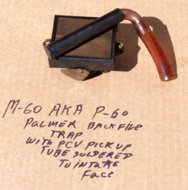 |
William Champion
Visitor
| | Posted on Monday, April 03, 2006 - 07:55 am: |
|
Great picture from Dick. On my P-60 in a Morgan 35, someone had actually installed tubing from the elbow on the manifold to an above the waterline thru hull. Didn't do anything but give me a fair amount of blowby in the engine compartment. I made a similar contraption using 1/2" copper pipe with a soldered pipe cap. Instead of a slot, I drilled small holes into the pipe and soldered to the back fire trap with the holes facing the cap. Works like a charm. |
Richard A. Day Jr.
Senior Member
Username: richardday
Post Number: 317
Registered: 11-2003
| | Posted on Wednesday, April 05, 2006 - 06:08 pm: |
|
That is the second time I have heard of the vent connected to a thru hull. I don't know what that would do to help the situation. Glad it worked out for you. It ain't rocket science!!! Just seems like it to most boat yard mechanics. My oldest son when he was in high school worked for one of the big Annapolis boat yards in summer time and the yard foreman told him to ground the negative of the starting battery to the wing nut on the top of the carburetor backfire trap. Needless to say Rick refused to do so and the foreman was not pleased. Rick told him he would report that connection to the boat owner and warn him it could burn up his boat the instant he hit the starter switch. The Foreman backed down but didn't like Rick's refusal to follow orders no matter how dangerous. You have to wonder how many other problems incompetent yard help introduce into otherwise excellent condition boats. |
|
|
|


|