| Author |
Message |
    
miro
| | Posted on Thursday, October 10, 2002 - 10:37 am: | 


|
I am getting a new old boat ( late 1930's) and I want to install a Kitchen rudder. In searching the net for info I found there is a USA patent ( no. 4895093) for a modern version of the Kitchen rudder.
My challenge is that I cannot open the image on the USA Patent Office web site. I'va asked others to try to open the Image page - to no avail. Can anyone out these open the Image?
miro |
    
andrew
| | Posted on Thursday, October 10, 2002 - 11:32 am: | 


|
Miro,
Yes... I have opened the images on the USA patent site... post the full url of the patent you are trying to get and I will try to open it and then save the image and email it to you.
Also... there is a full chapter on "The Kitchen Rudder" in Weston Farmer's book FROM MY OLD BOATSHOP. It has some stetches of it, but they are not dimensioned... not suitable for construction.
Regards,
Andrew |
    
bob
| | Posted on Friday, October 11, 2002 - 12:22 am: | 


|
i was able to load apple quicktime aand then netscape prompted me to load a plugin that it chose. it works fine and was able to view the files bob........ |
    
rbprice
| | Posted on Friday, October 11, 2002 - 08:09 pm: | 


|
Here's a link to the patent. Unfortunately, one cannot print it since the UPTO makes its living charging for copies. 8^(
http://patimg1.uspto.gov/.piw?docid=US001186210&SectionNum=1&IDKey=CC86FBA35B7C&HomeUrl=http://patft.uspto.gov/netacgi/nph-Parser?Sect1=PTO2%2526Sect2=HITOFF%2526p=1%2526u=/netahtml/search-bool.html%2526r=3%2526f=G%2526l=50%2526co1=AND%2526d=p~~~%2526s1=1,186,210%2526OS=1,186,210%2526RS=1,186,210 |
    
andrew
| | Posted on Friday, October 11, 2002 - 11:33 pm: | 


|
I couldn't get to it from the link Bob provided above... that link might include a session number that timed out... but I went to the search page:
http://patft.uspto.gov/netahtml/srchnum.htm
... and entered the number: 4895093 and it worked fine.
If yours doesn't load Miro it is probably due the "QuickTime" plug-in. You could try downloading the latest one.
Interesting patent, very recent, 1990.
Regards,
Andrew |
    
miro
| | Posted on Sunday, October 13, 2002 - 08:53 pm: | 


|
Yes the problem was the plug in . I was able to download it from the USAPTO web site and was able to open the drawings. I wonder if these things work?
miro |
    
raymond
Visitor
| | Posted on Monday, July 04, 2005 - 10:54 pm: | 


|
Miro, I have driven a 33ft survey launch with a "Kitchin" rudder, they give very precise control as needed for surveying around wharves and jetties |
    
Gerald
Visitor
| | Posted on Saturday, September 16, 2006 - 11:09 am: | 


|
Hi Raymond,
Do you have any photos of your launch that you could post, particularly ones showing the Kitchen Rudder?
Regards,
Gerald |
    
Jorma Koivunen
Visitor
| | Posted on Thursday, September 13, 2007 - 03:17 pm: | 


|
Is there anyone who makes these kitchen rudders? |
    
barry
Advanced Member
Username: barry
Post Number: 46
Registered: 02-2006
| | Posted on Friday, September 14, 2007 - 10:28 am: | 


|
http://www.oldmarineengine.com/discus/messages/1/95580.html
Refer to this post about my Kitchen Rudder.
If you are interested in this device, please let me know where you are located and also more information including images of the vessel you wish to fit with a Kitchen Rudder.
regards
Barry |
    
paulgray
Senior Member
Username: paulgray
Post Number: 53
Registered: 05-2003
| | Posted on Friday, September 14, 2007 - 06:01 pm: | 


|
Try Google patents- it is on the home page. You can then do a save-as on images of pages. I used to use quicktime then went to this- give it a try.
P |
    
tlane0
New member
Username: tlane0
Post Number: 1
Registered: 02-2008
| | Posted on Sunday, February 24, 2008 - 12:28 am: | 


|
I have 1967 Luhrs 32 sedan. When I Ran it the first time backig out from the slip I realized that to make a right hand turn I would have to do 270 to the left.the stern walked to the right (left hand prop) and that was that. I installed a kitchen rudder and now I can back with complete control and also I can partial close for slow trolling. I use a 12 volt hydraulic actuator and cylinder to open and close. |
    
haylingbillyboat
New member
Username: haylingbillyboat
Post Number: 1
Registered: 10-2009
| | Posted on Thursday, October 15, 2009 - 04:18 am: | 


|
I have some close up photos of details of the Kitchen rudder assembly that is in the Basildon Motor Boat Museum in the UK....if anyone wants them......
[email protected] |
    
haylingbillyboat
New member
Username: haylingbillyboat
Post Number: 2
Registered: 10-2009
| | Posted on Thursday, October 15, 2009 - 01:46 pm: | 


|
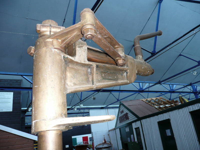
Kitchen rudder photo 1 - rudder head - lowest bracket is a horizontal vee shape and is where it would have bolted to transom so would be fixed. Whole assembly rotates above this bracket. You cannot see the vee in this shot as camera is horizontally level with the bracket
phot0 taken at Basildon Motor Boat Museum, Essex, England, sept 09.
 |
    
haylingbillyboat
New member
Username: haylingbillyboat
Post Number: 3
Registered: 10-2009
| | Posted on Thursday, October 15, 2009 - 05:24 pm: | 


|
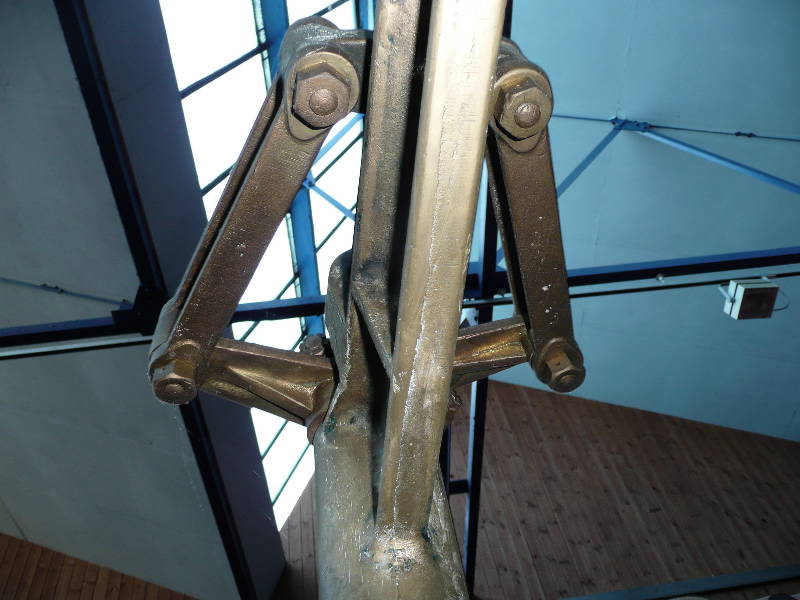
This photo shows the same area ( tiller ) as photo one but now you are looking vertically up to the ceiling, along the main vertical axis of the assembly.
You can see the arms attached to the 2 concentric rudder shafts, which run down inside the bronze tiller casting.
you can see the actuating links, and the method of fixing to the acme thread.
Remember there is no 'boat' it rotted away a long time ago. |
    
haylingbillyboat
Member
Username: haylingbillyboat
Post Number: 4
Registered: 10-2009
| | Posted on Thursday, October 15, 2009 - 05:45 pm: | 


|
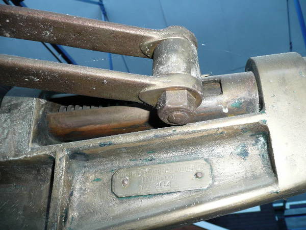
TILLER AREA - thread and plaque
The plaque is the maker's plate - it says:
KITCHEN'S REVERSING RUDDER CO
LIVERPOOL
No 904
You can see the acme thread on the shaft protected by a sheath or cover with a slot in it otherwise the arms would twist.
I must admit I am not sure if there is only one continuous thread or if there are 2 threads , one left hand, one right hand.And is there one collar on the thread or two - moving in opposite directions ? I tried to operate the machanism but without the wheel on the end of the shaft I couldn't move it. I did use one of these a few times when I was in the British Royal Navy - 1975. |
    
haylingbillyboat
Member
Username: haylingbillyboat
Post Number: 5
Registered: 10-2009
| | Posted on Friday, October 16, 2009 - 03:14 am: | 


|
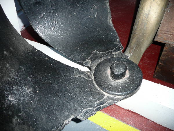
Here you can see the bronze skeg, and the bottom joint of the two fabricated (riveted) sheet steel/iron buckets, both hard over to port and in the nearly full astern position, i.e closed together.
The propellor itself, and the prop shaft is missing, otherwise you would have been able to see at least part of a prop blade in this shot.
You can see the how the bottom bearing works . |
    
haylingbillyboat
Member
Username: haylingbillyboat
Post Number: 6
Registered: 10-2009
| | Posted on Friday, October 16, 2009 - 03:37 am: | 


|
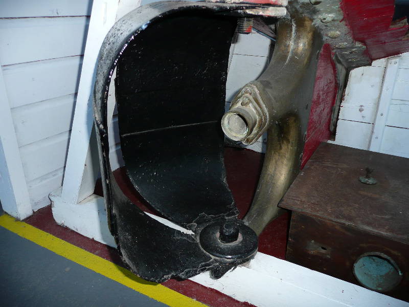
This shot shows both buckets, the skeg and the red remains of the wooden keel and hull, as well as the prop shaft aperture.
If you look closely on the right hand bucket, the horizontal white line is in fact one of the two riveted joints - the lower one.
Each bucket is made of 3 pieces, 2 curves and a straight.
If you now look closely at the left hand bucket you can see the corresponding 'step' where the joint is on that one. You can also see the top joint in this left hand bucket..all very simple - a 3 piece riveted fabrication.
I dont think the buckets will nest in each other, I think they probably but up againt each other in the fully astern ( as in photo ) or fully ahead position.
Unfortunately I did not get a very good shot of the crucial top mounting, but there is a gland, and then each bucket is on its own shaft or tube, all mounted concentrically...so you have 3 nesting layers of tube.
There is not alot to see externally, you have to guess at the workings.
The retaining nut is missing, but obviously fitted on the threaded part of the shaft where the dab of red paint is.
Again - its not clear how the middle shaft is fixed to its bucket, must be some sort of flange I think |
    
haylingbillyboat
Member
Username: haylingbillyboat
Post Number: 7
Registered: 10-2009
| | Posted on Friday, October 16, 2009 - 04:09 am: | 


|
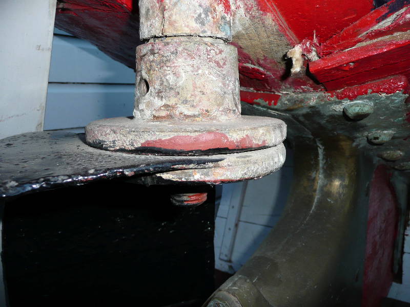
OK so I was lieing...here is a photo of the top of the rudder, so you now have 4 nested tubes...gland, rudder stock, one bucket, second bucket.
You can see the both buckets and the flanges joining the buckets to the shafts
the prop shaft gland is just visible lower down |
    
haylingbillyboat
Member
Username: haylingbillyboat
Post Number: 8
Registered: 10-2009
| | Posted on Friday, October 16, 2009 - 04:47 am: | 


|
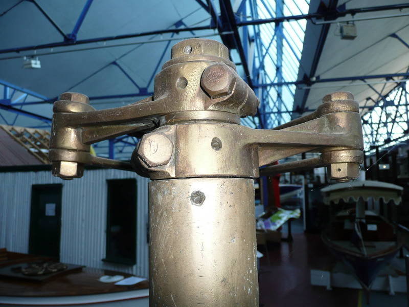
Up at the top of the rudder stock again.
View from directly astern.
Shows the 3 tubes, stock, outer bucket , inner bucket and the yokes and connecting rods - method of fixing.
And the lubricating holes - in fact this example is seized solid . |
    
haylingbillyboat
Member
Username: haylingbillyboat
Post Number: 9
Registered: 10-2009
| | Posted on Friday, October 16, 2009 - 05:40 am: | 


|
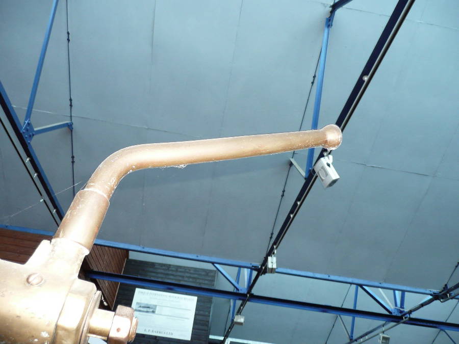
This shows the actual tiller itself, ( the perspective is odd because it was way above me and teh camera) and the end of the screw thread spindle, where the operating wheel should be - think a small lathe type feed wheel here, with a finger sticking out as on a mill or lathe.
I have seen posted elsewhere that you needed 3 hands to operate these things - one on the tiiler handle to steer, one to wind the wheel and one to operate the throttle.
This is not the case, the engine is run at constant revs, when manouevering and all the acceleration/deceleration is done on the buckets.
if you slow the engine down when you want to stop or go astern , then you are missing the point, aswhat you are doing at all times is controlling the prop wash with the buckets - ahead, astern, neutral, and in between.
And the actual direction of the propwash is adjusted with the tiller. |
    
haylingbillyboat
Member
Username: haylingbillyboat
Post Number: 10
Registered: 10-2009
| | Posted on Friday, October 16, 2009 - 05:53 am: | 


|
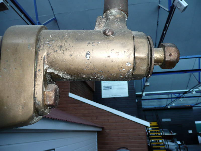
This shows the tiller itself disappearing off vertically out of the picture - it looks as if it is silver soldered on to the main casting.
...and the end of the screw thread spindle - minus it's operating wheel.
And the way in which the threaded spindle is inserted into the horizontal tiller casting and retained by a sort of gland arrangement. |
    
haylingbillyboat
Member
Username: haylingbillyboat
Post Number: 11
Registered: 10-2009
| | Posted on Friday, October 16, 2009 - 06:00 am: | 


|
That is all the photos I have of the Kitchen rudder gear.
Please don't fall into the trap of referring to it as a KITCHENER Rudder, because its not - its named for and by the British Admiral Kitchen.
Here is a link to the website of the museum holding this exhibit, plenty of ic engines there especially outboards and 1920s-80s racing craft etc. Entry is free.
www.motorboatmuseum.org.uk
The Motorboat Museum
Wat Tyler Country Park
Pitsea Hall Lane, Basildon
Essex, SS16 4UH
UK
from the US phone 00 44 1268 550077
in addition there is an extremely good article at :
http://en.wikipedia.org/wiki/Kitchen_rudder |
    
miro
Senior Member
Username: miro
Post Number: 398
Registered: 11-2001

| | Posted on Friday, October 16, 2009 - 09:28 am: | 


|
Thanks for posting this valuable stuff - I'm finally getting back to the restoration of a 1910 fantail launch ( 18ft) - you'll note my original post from many years ago - doesn't seem that long.
I like the idea of an electrically operated bucket position system, so that I only have to think about the rudder position.
I won't get this done till July / Aug next year, but this might just speed things up.
After that, maybe it would be great to take the boat to the LA bateaux-fest the following March - any excuse to get warm.
Thanks gain,
miro |
    
haylingbillyboat
Member
Username: haylingbillyboat
Post Number: 13
Registered: 10-2009
| | Posted on Friday, October 16, 2009 - 01:12 pm: | 


|
Try reading this website from a true expert, and on your side of the Atlantic too.....
http://www.proboat-digital.com/proboat/200608/?pg=63
The author of the article is David Gerr..and the web says this about him:
Dave Gerr founded Gerr Marine, Inc., in 1983. Based in New York City, the firm designs both yachts and commercial vessels, and probably works on a wider assortment of boat types than any other design office—sail and power, yacht and commercial, monohull and multihull.
In 1979, Gerr started as a naval architect at MacLear & Harris, Inc., where work concentrated on megayachts, power and sail, and where much pioneering design in large and small multihulls was done. Gerr also has built, repaired, and lofted a wide variety of boats, and has supervised FRP production on the shop floor.
In addition, Gerr performs specialized surveys for insurance companies and law offices. He has been an expert witness on a wide variety of cases, from marine-related homicides to routine insurance and damage suits.
Gerr is the author of Propeller Handbook, The Elements of Boat Strength, The Nature of Boats, and Boat Mechanical Systems Handbook, all published by International Marine/McGraw-Hill. He has written over 400 articles on boats and boat design that have appeared in almost every major boating magazine, and he has been a contributing editor for Yachting, Offshore, and Boatbuilder magazines.
A graduate of the Westlawn Institute of Marine Technology, Gerr studied physics at New York University and industrial design at Pratt Institute. A Fellow of the Royal Institution of Naval Architects (RINA), Gerr is also the director of the Westlawn Institute of Marine Technology. |
    
searcher
Senior Member
Username: searcher
Post Number: 365
Registered: 10-2004
| | Posted on Saturday, October 31, 2009 - 09:12 pm: | 


|
Here is another kitchen rudder setup.
 |
    
tlane0
New member
Username: tlane0
Post Number: 2
Registered: 02-2008
| | Posted on Saturday, October 31, 2009 - 11:32 pm: | 


|
here are links to my kitchen rudder:
http://www.fidalgo.net/~tlane/rudder1.mpg
http://www.fidalgo.net/~tlane/rudder2.avi |
    
haylingbillyboat
Member
Username: haylingbillyboat
Post Number: 14
Registered: 10-2009
| | Posted on Sunday, November 01, 2009 - 05:03 am: | 


|
I have watched both these 'tlane0' videos - very impressive, especially the idea of having powered actuation, saves a lot of hand wheel turning at a time of maximum brain concentration. |
    
j matheson
Visitor
| | Posted on Wednesday, July 17, 2013 - 11:02 am: | 


|
I have a complete Kitchener rudder for sale.Glasgow Scotland. |
    
kitchensrudder
New member
Username: kitchensrudder
Post Number: 1
Registered: 01-2018
| | Posted on Sunday, January 07, 2018 - 11:08 am: | 


|
Hi. Do you know the year that Kitchen�s Rudder was made or the year it was used? |
    
richarddurgee
Senior Member
Username: richarddurgee
Post Number: 4073
Registered: 11-2001
| | Posted on Sunday, January 07, 2018 - 02:26 pm: | 


|
*
https://en.wikipedia.org/wiki/Kitchen_rudder
US patent filed 1916, I have seen ads in the very early 1920's and an article in 1925 That McNabb Kitchen expanded their
mfging plant in Bridgeport, Ct--
Lots of info on line !
* |
    
bcm
Senior Member
Username: bcm
Post Number: 78
Registered: 11-2009
| | Posted on Monday, January 08, 2018 - 09:22 am: | 


|
The information that you requested, also a link to a youtube video about Kitchen Rudder, is at this site.
www.goslowboat.com
Until about 1960, British ships of Cruiser size and larger carried several open 32 foot cutters. These used Kitchen rudders, probably because maneuverability was important as they were often used for rescue work. At least two cutters found their way to Canada. Several ended up in Australia, as they were included in an aircraft carrier purchase by the Australian Navy. It is interesting to note that these cutters were also equipped with conventional reverse gearing that was usually locked out. This unusual practice confirmed the advantage of their Kitchen gear.
Barry |
    
robert
Senior Member
Username: robert
Post Number: 921
Registered: 07-2003
| | Posted on Wednesday, January 10, 2018 - 12:37 pm: | 


|
http://www.goslowboat.com/files/rudder2.jpg
I suspect the flow and therefore the effectiveness of this rudder in the closed position would be greatly increased if the two halves of the rudder were made much more rounded as per the original shown above. Much more of the propeller wash would then be redirected when the rudder was closed, and with less turbulence and obstruction of the flow created.
For someone wanting to build such a rudder, a good source of the necessary forms might be any kind of steel or preferably stainless steel ball/buoy or similar rounded shape.
Another question is the degree to which the rudder halves when closed need to complete a half circle; the original rudder above appears to complete only about a third of a circle. The result being that the prop wash that has been redirected by the rudder shells is not "turned" as radically and therefore is not slowed or obstructed as much by the flow continuing to come off the prop: it can in effect "squeeze past" that flow and is directed outwards at what looks like maybe a 30-40 degree angle.
This might seem less effective than a redirection of the flow that comes closer to the centerline of the vessel, but the fluid dynamics mentioned would contradict that I believe.
The other limitation of course is the turbulence and resistance created by the two halves when in the fully open position increases with every increase in their curvature. That is the virtue of the design in the photo above: it creates minimal resistance in the open position being straight sided. A case could be made that this is the most desirable option!
The fact that the two halves constituted something of a guard around the propeller was probably attractive to the Admiralty as well, at least in rescue operations. |
    
bcm
Senior Member
Username: bcm
Post Number: 80
Registered: 11-2009
| | Posted on Thursday, January 11, 2018 - 02:05 pm: | 


|
Robert,
Your analysis is both interesting and useful.
Reversing capability is only one feature of a Kitchen Rudder.
Maneuverability including speed control, direction control, stern thrust etc provided by the device is much better than provided by a standard transmission. The video at www.goslowboat.com is intended to display this maneuverability.
If interested when viewing the video, focus on all Kitchen Rudder features, clam shell position ,tiller manipulation, then how the boat behaves particularly directional control when clam shells are closed or almost closed and when stern thrust is applied.
I have attended many boat shows and other Kitchen Rudder demonstration however I have failed to attract interest in understand this remarkable capability, thus the reason for the video at www.goslowboat.com.
As an example at minute 2 in the video, the boat is stationary. If this were a standard transmission propeller would be detached from engine. Boat would float without control until transmission is engaged. When using Kitchen Rudder engine and propeller remain connected, thus very subtle moment of tiller and clam shell crank provides instant control of boat position, direction and speed.
Barry |
    
kitchensrudder
New member
Username: kitchensrudder
Post Number: 2
Registered: 01-2018
| | Posted on Saturday, January 13, 2018 - 06:11 pm: | 


|
Thank you very much. I really appreciate the information you have posted.
I am trying to guess the date for a Kitchen Rudder Steering Wheel and as I could see the number in that Kitchen Rudder at the beginning of the conversation I wanted to know the exact date of that one to guess the date of the wheel.
I have seen that 4000s were commercialized in the 50s and being patented during the 20s there are 30 years to reach that number.
Being a period of wars their production must have been larger during the 30s and 40s.
It is certainly a very beautiful and unique piece and I wanted to collect as much information as possible from it for it not to be sold under its real value. |
    
robert
Senior Member
Username: robert
Post Number: 922
Registered: 07-2003
| | Posted on Tuesday, January 16, 2018 - 02:08 am: | 


|
Barry I'm convinced, I suspect unfamiliarity and complexity and resulting fears of loss of use were the main obstacles, and perhaps still are? Although now we have hydraulic drives which get the shaft out of the way and allow a full nozzle effect in all directions.
Looking at the original shown above I should amend my comment about possible sources of such forms in steel for the amateur builder: the original is somewhat flat in the middle, which of course helps the flow to be redirected outwards where a perfectly round back would tend to compress and trap the flow rather than redirecting it outwards. |
    
bcm
Senior Member
Username: bcm
Post Number: 81
Registered: 11-2009
| | Posted on Wednesday, January 17, 2018 - 02:34 pm: | 


|
Robert,
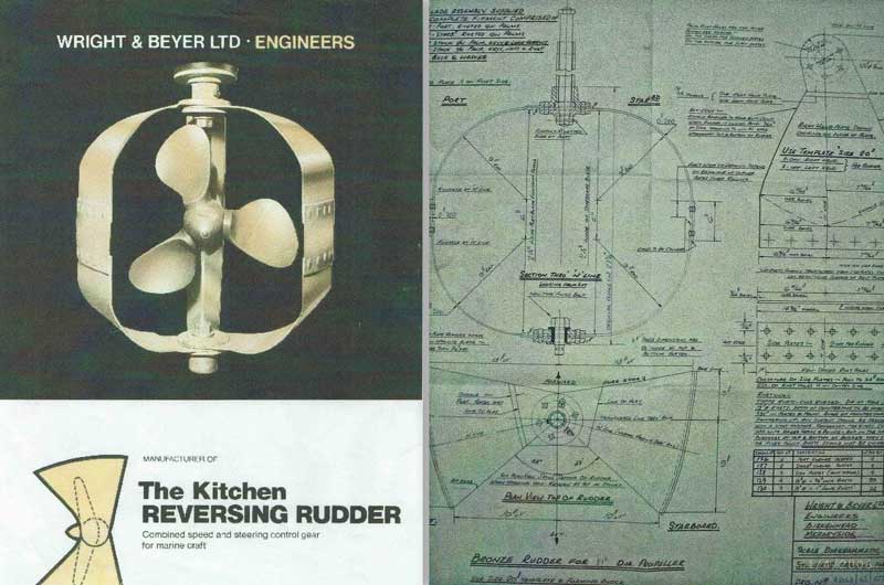
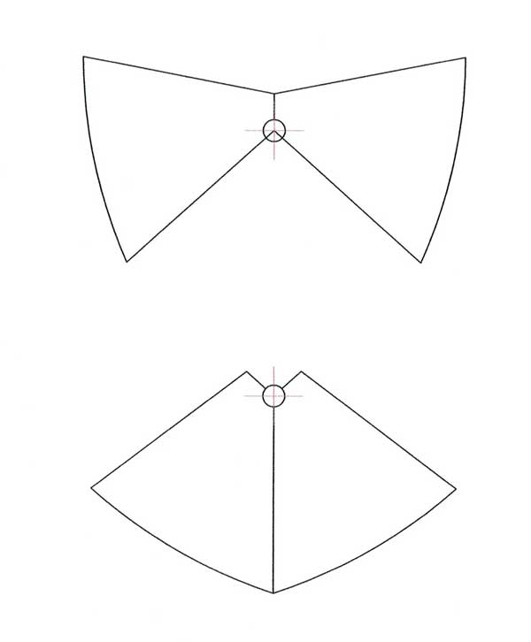
Here is more information to ponder. This shows the shape and dimensions of the clam shells as manufactured for the Admiralty, the battleship version per the images at beginning of this post.
Since these are very different compared to the usual cylindrical shape. I suspect some evaluation and testing was conducted prior to their multi use by the Admiralty thus a reasonable conclusion that this is a preferred shape.
Note when open the clam shells form a convergent nozzle, presumable to accelerate the exiting water stream.
If I were to build another rudder, I would consider using the Admiralty design.
Barry
 |
    
jb_castagnos
Senior Member
Username: jb_castagnos
Post Number: 1357
Registered: 07-2002

| | Posted on Thursday, January 18, 2018 - 08:36 am: | 


|
It looks like the rudder in the picture is shown with a reversing propeller. |
    
robert
Senior Member
Username: robert
Post Number: 925
Registered: 07-2003
| | Posted on Thursday, January 18, 2018 - 03:18 pm: | 


|
Indeed, or one with replaceable blades.
That nozzle effect in the open position is interesting alright. Did it in fact improve efficiency over an open prop!? |
    
bcm
Senior Member
Username: bcm
Post Number: 82
Registered: 11-2009
| | Posted on Friday, January 19, 2018 - 09:51 am: | 


|
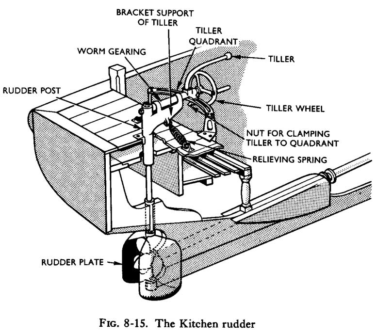
When I refer to the British Admiralty, this is the British Navy. There is no purpose for a reversing propeller for use with a Kitchen Rudder. I suspect the propeller is just a very heavy duty design (battleship grade)that fits military specifications.
Of interest is the following information published by the Admiralty. This refers to the Kitchen Rudder in the images in this posting by Andrew Berry, 2009, the same rudder at Basildon Museum UK.
Barry
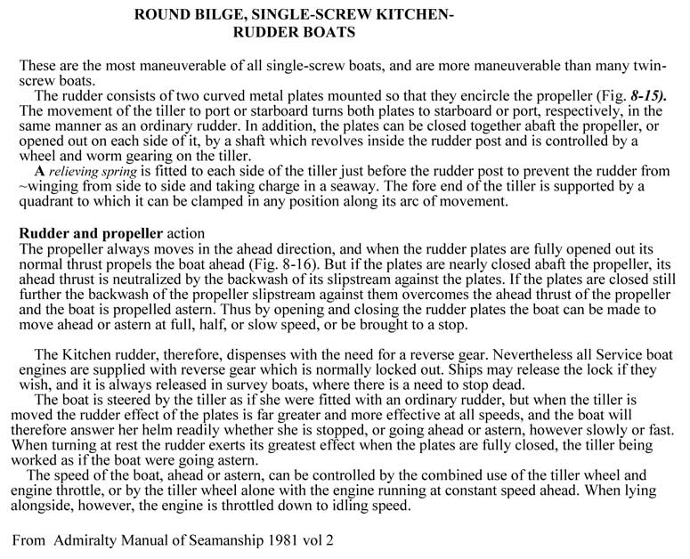 |
    
robert
Senior Member
Username: robert
Post Number: 928
Registered: 07-2003
| | Posted on Friday, January 19, 2018 - 11:39 am: | 


|
Looking at that last illustration, it is clear that the nozzle effect can also be on the forward side of the propeller as well: compressing the water flowing onto the prop and thereby increasing its efficiency? |
    
bcm
Senior Member
Username: bcm
Post Number: 83
Registered: 11-2009
| | Posted on Friday, January 19, 2018 - 02:05 pm: | 


|
Robert,
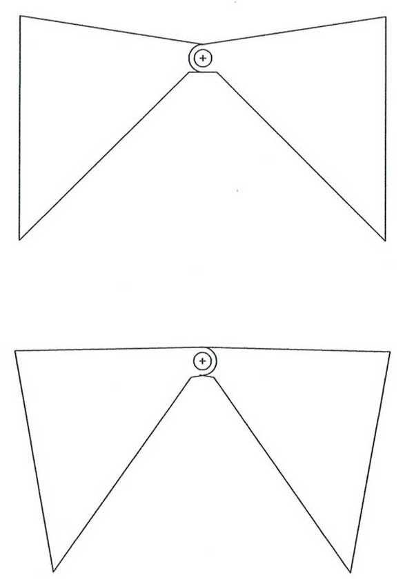
The question is... does a Kitchen Ruddernozzle effect result in more boat speed? This is Kort nozzle effect.
I intend to attempt to answer this question by operating my boat with clam shells open when wind and current are zero, checking boat speed using GPS then closing clam shells about 10 degrees then again checking boat speed, do test several times.
I'll do this test in June when ice is off the lake.
Refer to sketch below. This is the cylindrical design.
Barry
 |
    
Mark Alton
Visitor
| | Posted on Tuesday, March 06, 2018 - 12:50 pm: | 


|
Hello all, as this is possibly my first comment.
I have an old Manchester ship canal survey launch that was originally fitted with a kitchen rudder, but looks to have been modified to operate in a conventional fashion only.
I really want to restore the functionality of this wonderful device, to enjoy the benefits of increased maneuverability and control as she's now inland on the River Trent.
Any advice, ideas, spare parts (the scissor arms and screw jack are missing), would be very gratefully accepted.
Yours in hope,
Mark Alton
 |
    
bcm
Senior Member
Username: bcm
Post Number: 84
Registered: 11-2009
| | Posted on Wednesday, March 07, 2018 - 11:29 am: | 


|
Mark,
Considerable Kitchen Rudder activity occurred in UK before, during and after WW2. The supplier of Kitchen Rudders appears to have been Wright & Beyer, Birkenhead, Merseyside.
Kitchen Rudders were used by the Admiralty for close quarter maneuvering of open vessels. These were transom mounted and coxswain operated using the tiller mounted screw arrangement described elsewhere in this post.
Identical rudders were also used after WW2 to provide superior maneuverability for survey vessels.. Yours is this application. In this case control was by means of dual wheels at an inside steering station.
Rudder � coxswain communication required a complex system of cables, pulleys, levers and springs.
I suggest you study the information at this link particularly starting at page 8.
https://www.scribd.com/document/22236032/Kitchen-Rudders-Going-Full-Circle
Additional information is at this link.
https://www.scribd.com/doc/22985018/Kitchen-Rudders-Their-Inventor-and-Some-Appl ications
A survey vessel, MVS ranger One was in use Belfast Harbour as recent as 2006. Ranger One was offered for sale since 2006 thus is probably operational somewhere in UK. Ranger One would use the same inboard arrangement to control Kitchen Rudder as would your vessel thus would provide an exceptional information source.
I can provide you with an email contact that might help locate Ranger One. Email me if you wish this this contact.
Here is an excellent video showing a recent Kitchen Rudder installation with inside control like yours. Probably would require a trip to Norway to experience firsthand.
https://www.youtube.com/watch?v=vi0Sdkbooek
Here is a video of my Kitchen Rudder. To experience this first hand would require a trip to Canada !!
https://www.youtube.com/watch?v=2R-AO3nZpyo
Barry Millar |
    
nautibits
New member
Username: nautibits
Post Number: 1
Registered: 07-2020
| | Posted on Saturday, July 04, 2020 - 01:51 pm: | 


|
Bit late to the party I am afraid, but I hope some of this is of interest still...
I had the pleasure of owning an ex RN 32' cutter during the 70's. She came off the Ark Royal (09) before they scrapped her in Devonport.
When I emigrated to Canada I had to scrap the hull, but not before removing the 600lbs of bronze Kitchen Rudder and assorted fittings.
I now have the Kitchen Rudder mounted in its original configuration. A great conversation piece and nostalgia.
At some point I would like to re-install the gear on a suitable boat.
Any suggestions?
Here is 'Darius' in all her past and present glory, together with original MOD drawings:
https://photos.app.goo.gl/jYw7MRWNUgdUYUMu8 |


