| Author |
Message |
    
searcher
Senior Member
Username: searcher
Post Number: 85
Registered: 10-2004
| | Posted on Sunday, March 05, 2006 - 12:23 am: | 


|
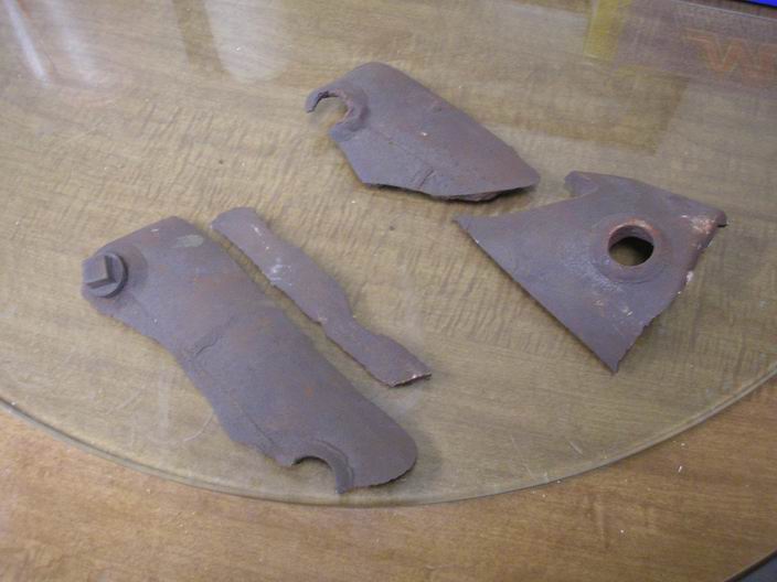
It getting hard to find old engines to restore up here in Maine, I think all the good ones have gone to collectors south of here. However, we do the best we can with what we have available.
(C. L. Barker, Norwalk, Conn. 1 1/2 hp)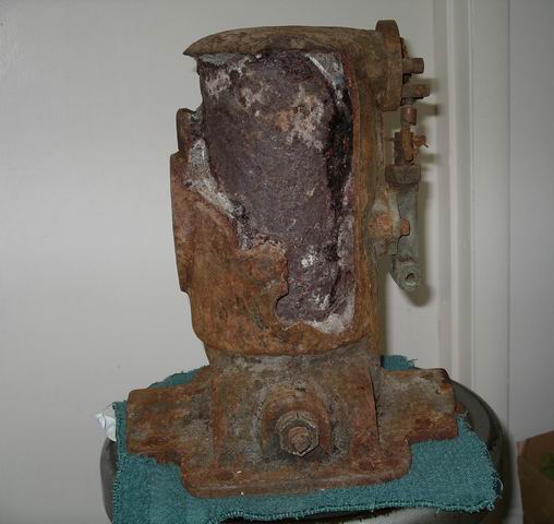 |
    
solarrog
Senior Member
Username: solarrog
Post Number: 132
Registered: 03-2002

| | Posted on Sunday, March 05, 2006 - 12:30 am: | 


|
alittle glue, and paint it should be fine.
who ever used this one got their moneys worth. Or possibly this was what they changed out when they put the motor back in service, You didnt say if there was more |
    
robert
Senior Member
Username: robert
Post Number: 101
Registered: 07-2003
| | Posted on Sunday, March 05, 2006 - 02:44 am: | 


|
Looks like it went over the side in pieces, as they often did! |
    
searcher
Senior Member
Username: searcher
Post Number: 86
Registered: 10-2004
| | Posted on Sunday, March 05, 2006 - 01:24 pm: | 


|
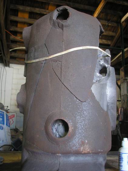
Actually, this engine was probably fairly whole on the day it was retired from its work in salt water. Sitting around in the barn for most of a century allowed the iron/salt expansion within the water jacket to break the engine down right where it sat. The stuff in this water jacket is quite different from the common shaley iron I usually see in water jackets, this is as hard as concrete.
There was a can of usable parts as well as the flywheel, base, etc., that came with the engine so it was worth hauling home for the parts (although my wife would probably offer another opinion). |
    
gregoryan
Member
Username: gregoryan
Post Number: 9
Registered: 09-2004
| | Posted on Thursday, June 08, 2006 - 08:35 am: | 


|
LOL, What fun we have, showing and telling! Yeah, i can appreciate that ol' thing too!
They are sculptures of lived experience of a time where most of us perhaps came from in our previous lives! |
    
george_iv
Advanced Member
Username: george_iv
Post Number: 37
Registered: 07-2003

| | Posted on Friday, June 09, 2006 - 10:03 am: | 


|
Well, I have an idea. I just talked to dad and he say's he can fix it, and is willing try. It'll take a while and he's not interested in hunting parts that aren't in the basket. If you are up for this and your wife can bear to part with the engine for a few months, send ALL the parts to me and we'll do the magic wand thing to it. We'll keep everything on this forum, so everyone knows what's going on, and I'll post pictures of the progress.
This is a serious offer, and I look forward to your reply!
George IVy |
    
jb_castagnos
Senior Member
Username: jb_castagnos
Post Number: 135
Registered: 07-2002
| | Posted on Friday, June 09, 2006 - 07:30 pm: | 


|
George, it would be less of a challenge to start from scratch, but I know your dad can handle it, should make an interesting story.
J.B. |
    
richarddurgee
Senior Member
Username: richarddurgee
Post Number: 1139
Registered: 11-2001

| | Posted on Saturday, June 10, 2006 - 02:41 pm: | 


|
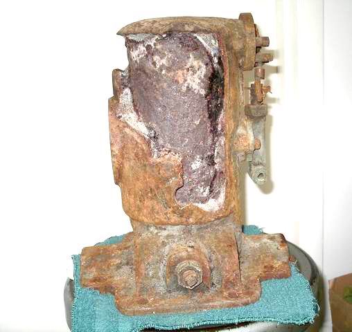
This looks like an early Barker 1910 or older.
The flywheel should have a curved slot through it for a stud with nut to adjust the timing!
Whatever the odds are on fixing this one my money's on George !
 |
    
searcher
Senior Member
Username: searcher
Post Number: 115
Registered: 10-2004
| | Posted on Sunday, June 11, 2006 - 09:36 pm: | 


|
Geroge iv,
Richard's comment "Whatever the odds are on fixing this one my money's on George!" reminds me of a crusty old mine manager by the name of Paul Matthews I worked under some 35 years ago. If Paul thought he could fight his way through Hell and make it to the other side, I would have gone along for the adventure half believing he just might pull it off.
I am quite interested to hear more about what you propose. Sounds like fun. Are there conditions attached to your offer and do I get the engine and all its parts back in the end?
As Richard suggests, I think the Barker is a very early one of 1 1/4 hp, the smallest size Barker made. It does have the timing arrangement as Richard suggests. The patent date cast into the base is November 4, 1902. As I recall, that is a patent for the method of greasing the bearings, not a patent for the engine itself. There is no tag on the engine. Rather, C.L.Barker, Norwalk, Conn. is cast into the water jacket in small letters just to the lower right of the ignitor.
I have all of the water pump and make and break parts, the base, crankshaft, and flywheel. I have the bronze connecting rod but am missing the piston and the connecting rod bearing cap. The grease cups and oilers are missing but those items were most likely off-the-shelf stuff. The original mixing valve may well have been of Barker design. I don't think it ever had thrust bearings.
The Barker ads appear with great regularity from at least the February 1906 issue of The Rudder magazine (may appear earlier than that, I just didn't check) until well into the 1920's. In all that time, Barker ran only two versions of the ads and without any change. Presumably, the engine itself didn't change much either and a 1920 Barker brochure I saw would bear that out, at least for the smaller, single cylinder engines. |
    
george_iv
Advanced Member
Username: george_iv
Post Number: 38
Registered: 07-2003

| | Posted on Tuesday, June 13, 2006 - 12:11 pm: | 


|
Here are some more details...
What I propose: I propose to fix the cylinder water jacket. This will entail a special cleaning of all parts. After the water jacket and other cast iron parts are cleaned and fixed, they will be coated with an epoxy primer inside and out. I will post pictures of the steps along the way on OME and on my website.
What I need: I will need all of the parts, i.e. - water jacket pieces that exist in whatever condition, all accessories (water pump, timer, etc.) so mounting and hole locations can be determined, heavy parts like flywheel and base are also a good idea to have on hand. Pictures and notes are very helpful when doing this type of reconstruction. We recently finished a Termite/Detroit and luckily there are numerous places to glean information. I will need help with the Barker in this respect, so anything you can furnish will be appreciated.
Terms: I don?t want to incur any out-of-pocket expenses. I?m basically giving the labor and shop time away in hopes of preserving a piece of history. Some materials, supplies and the like I have and am willing to share, but if I buy it for the Barker, then you would be asked to pick up the tab. These things could include repair castings if you don?t have the broken parts, and rod for doing the welding. A note about the welding! We do fusion welding of cast iron and the finished parts are exactly as the original. We don?t use nickel rod, or JB Weld or any plastic fillers. It?s all iron. It looks, feels, acts just as the original. You will not be able to tell the difference in repaired and original.
Yep the engine is still yours...
George IVy |
    
bob holcomb
Visitor
| | Posted on Tuesday, June 13, 2006 - 10:33 pm: | 


|
george..... i looked up fusion welding and it describes everything from oxy acetyline to lazers which process are you using?????
http://www.staff.ncl.ac.uk/s.j.bull/mmm373/WELD/sld001.htm
also have been playing around with this for years and have seen cylinders so badly affected by the salt water they literally crumble apart i know the salt is a preserative and what affects the cast iron is the rest of the salt water chemicles.there was a good article here in ome on this process,i am just curios and maybe finding a better way to save these engines bob.... |
    
george_iv
Advanced Member
Username: george_iv
Post Number: 39
Registered: 07-2003

| | Posted on Wednesday, June 14, 2006 - 03:49 pm: | 


|
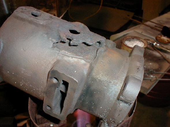
We use oxy acet for heat during the fusion welding. And heat is your friend... Use lots of it!!
As for the salt water embrittlement, we use a little know process involving a lot of heat and a lot of time. Basically from the time we start with the heating it may be 3 or 4 days before the part is allowed to cool below 525 deg f; this time also includes the welding time so the whole process is done at temperature. Once the parts are cooled down, they are sealed inside and out with an epoxy sealer. The parts will never again be as dry or devoid of moisture again and it only makes sense to seal the iron pores. The cast iron is basically as virgin as it was when it was poured at the foundry. This includes salts, minerals and the like. The iron oxide (rust) is converted into water vapor and iron dust, which resolves the swelling issues associated with the action of 'rusting'. The salts that worked there way into the iron are reduced and 'plate out' also.
I hope that explains some of the process. It's not trivial, but some things are worth the hassle.
George IVy
 |
    
searcher
Senior Member
Username: searcher
Post Number: 116
Registered: 10-2004
| | Posted on Wednesday, June 14, 2006 - 05:47 pm: | 


|
George,
C.L. Barker advertised consistently for more than 20 years that I am aware of but there seems to be few surviving engines, at least up here in Maine. So, I'm game for this project. I would like to see the Barker preserved for another generation or two. Despite its simplicity and obviously poor condition, I liked the Barker and have kept it in my office since acquiring it.
A photo record of the restoration process would be a terrific addition to this site. I only wish I was near enough to your shop to do the photography. Clearly, there will be a level of experience, ingenuity, skill, and art applied to this project that most of us would not otherwise get to see.
I am willing to pay the materials, just give me fair warning along the way so I don't get sticker shock.
In addition to engines, Barker apparently made related items. I have seen a C.L. Barker bronze gear driven water pump reminescent of those made by Orberdorfer and Sherwood.
I have also seen a C.L. Barker low tension magneto. The mag was run by a small pully designed for a thin 1" flat belt. The cast brass tag indicated running speed was 2400 rpm. |
    
george_iv
Advanced Member
Username: george_iv
Post Number: 40
Registered: 07-2003

| | Posted on Monday, June 19, 2006 - 11:07 am: | 


|
Sounds like a plan. Are you going to Mystic? If so I'll be there Friday and Saturday and we can meet. I can take the Barker home from there if that suits you.
Anybody else on the OME have info or pictures to share of similar Barkers?
George IVy |
    
searcher
Senior Member
Username: searcher
Post Number: 118
Registered: 10-2004
| | Posted on Tuesday, June 20, 2006 - 05:09 pm: | 


|
George,
I have never been to an engine show of any significant size so would like to get to Mystic (tried to get to a couple of other shows this spring but work keeps getting in the way). If it becomes obvious I cannot get to Mystic, I will try to find somebody else that is going. If that fails, I will build a suitable container on a pallet and ship it down. In the meantime, I will free up the ignitor and clean up the rest of the make and break mechanism, water pump, etc. |
    
searcher
Senior Member
Username: searcher
Post Number: 119
Registered: 10-2004
| | Posted on Saturday, June 24, 2006 - 01:05 pm: | 


|
George,
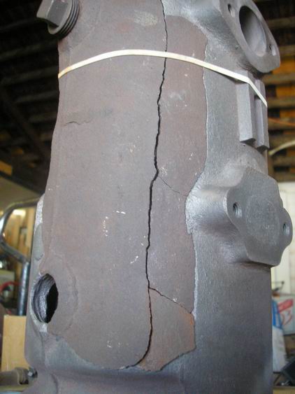
I pulled the Barker out this morning to measure the cylinder for a piston and to remove the ignitor, pump, etc., for cleaning. Looking inside the cylinder, I can see three serious cracks, one near the head, one about midway, and one very near the open end of the cylinder. All three exceed half the circumference of the cylinder and show some displacement. In other words, the entire cylinder is not far from breaking apart. I don't recall those cracks when I hauled it home, but, I probably didn't look either. I bought the engine for the parts and assumed it was not a candidate for restoration.
Anyway, the cylinder casting is obviously in pretty sorry shape, inside and out. Does it still sound like something you want to tackle? |
    
george_iv
Advanced Member
Username: george_iv
Post Number: 41
Registered: 07-2003

| | Posted on Monday, June 26, 2006 - 09:58 am: | 


|
It does sound pretty bad. I guess it's your call but it seems like you're starting with nothing so you don't have much to loose. Admitting defeat is not a problem, and a lot of the projects we take on are done so with this understanding.
From your earlier posts, it seemed a liner was going to be a necessity. Do you have bore and stroke dimensions? I can price the liner before we start with this info. No suprises, right?
As far as Mystic and picking up the engine, just let me know.
George IVy |
    
richardday
Senior Member
Username: richardday
Post Number: 346
Registered: 11-2003

| | Posted on Monday, June 26, 2006 - 09:39 pm: | 


|
I think there is a very nice Barker in the Rowayton, Ct.marine museum. They had one about 25 years ago and I would think it would still be there As I remember it it was very complete and not cracked or seemingly in poor condition. |
    
searcher
Senior Member
Username: searcher
Post Number: 121
Registered: 10-2004
| | Posted on Thursday, June 29, 2006 - 12:01 am: | 


|
I'm game George as long as you aren't discouraged. There are too many of us out there waiting to see what can be done with that poor little Barker to quit now. I am relatively new to the hobby and so have little idea what is possible and what is not. I will measure the bore and stroke in the morning. I have two possibilities of getting it to Mystic even if I can't get there myself. |
    
searcher
Senior Member
Username: searcher
Post Number: 122
Registered: 10-2004
| | Posted on Thursday, June 29, 2006 - 12:17 am: | 


|
Richard,
Thanks for noting the Barker in the Rowayton, Ct. museum. If anybody gets by there, I sure would appreciate photos so I can see what Barker may have used for the original mixer/carburetor, grease cups, color, etc. |
    
doug11k
Member
Username: doug11k
Post Number: 20
Registered: 12-2003
| | Posted on Thursday, June 29, 2006 - 10:12 am: | 


|
Here is an ad from October, 1910 Gas Power(if I can post it). 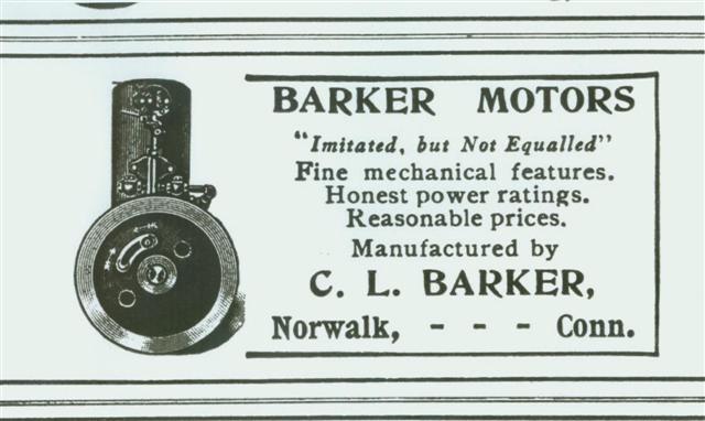 |
    
jb_castagnos
Senior Member
Username: jb_castagnos
Post Number: 149
Registered: 07-2002
| | Posted on Thursday, June 29, 2006 - 08:55 pm: | 


|
That's the first time I've seen a timing control in the flywheel, I guess it retimes the ignitor. |
    
robert
Senior Member
Username: robert
Post Number: 113
Registered: 07-2003
| | Posted on Thursday, June 29, 2006 - 09:07 pm: | 


|
Yes, and I can see how those two arrows might confuse a few simple fisher folk! |
    
searcher
Senior Member
Username: searcher
Post Number: 123
Registered: 10-2004
| | Posted on Thursday, June 29, 2006 - 10:10 pm: | 


|
While I have the Barker apart (I should say in pieces actually), I will photograph the connection between the timing device and the igniter mechanism and post them here. I need to clean it all up first, there is so much grease, rust, and gunk behind the flywheel that it is hard to recognize anything. |
    
searcher
Senior Member
Username: searcher
Post Number: 126
Registered: 10-2004
| | Posted on Monday, July 03, 2006 - 10:17 pm: | 


|
George,
As near as I can measure without proper calipers, the bore and stroke are: 4 1/8" bore, 4 1/4" stroke. I thought this engine was the smallest Barker made but in reality it is the next size up, i.e., 2 1/2 hp.
I know nothing about liners. Obviously, the internal diameter of the liner will be less than the original bore of the engine. I have several offers of pistons so will need to know what size piston to look for when the time comes. |
    
george_iv
Advanced Member
Username: george_iv
Post Number: 45
Registered: 07-2003

| | Posted on Saturday, August 26, 2006 - 11:32 am: | 


|
Hello all, Just a quick note about the Barker.
http://www.ghcoates.com/Barker.htm
I'll update the page and post here, on OME as time allows. I did it this way because the pictures are big and give a lot of detail.
George IV |
    
searcher
Senior Member
Username: searcher
Post Number: 134
Registered: 10-2004
| | Posted on Tuesday, August 29, 2006 - 12:13 am: | 


|
George,
Before the Barker hits the furnace, there is a knurled brass thrust washer on the crankshaft. I meant to take it off and put it in the parts jar before bringing it all to Mystic. However, in my haste to get some work out the door before I could leave for Mystic, I forgot to do that.
Neat site. This is going to be a real treat to see no matter how the Barker turns out. |
    
george_iv
Advanced Member
Username: george_iv
Post Number: 46
Registered: 07-2003

| | Posted on Friday, September 01, 2006 - 03:12 pm: | 


|
More stuff up on the page. Are the pictures too big? Let me know.
http://www.ghcoates.com/Barker.htm
Also updated some of the Tugboat pages.
http://www.ghcoates.com/Tugboat.htm
Have a great weekend!!
George IV |
    
richarddurgee
Senior Member
Username: richarddurgee
Post Number: 1199
Registered: 11-2001

| | Posted on Saturday, September 02, 2006 - 03:51 pm: | 


|
George
And Great stuff it is !
I have a new high powered PC with a 19 inch flat screen and it takes about 30 secs to download each photo so it may take quite awhile for older machines but I can count the grains in the old iron !
I like that patent date casted in and to see what that timing mechanism looked like, and most of all the subtle awarness of the years of experience, the capabilities and talent present to have the confidence to proceed with machining the crank bearings first !!
It's a Great weekend already . |
    
keith
Senior Member
Username: keith
Post Number: 144
Registered: 02-2002

| | Posted on Sunday, September 03, 2006 - 11:11 am: | 


|
George
Can you explain the temperature and time factor in the furnace and why it may take three times. What tells you when you have heated it enough? |
    
searcher
Senior Member
Username: searcher
Post Number: 137
Registered: 10-2004
| | Posted on Sunday, September 03, 2006 - 02:38 pm: | 


|
Terrific photos George. I was surprised to see that the bearings and other brass/bronze pieces did not melt. The two little puddles of metal must be babbit?
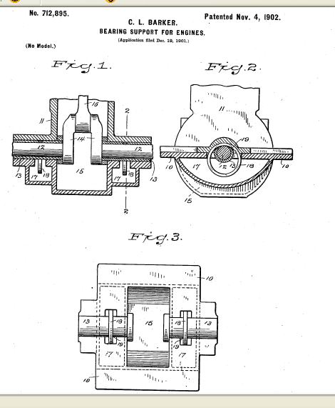
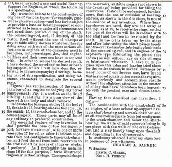
The November 4, 1902 patent date cast into the base of the Barker is a patent for the bearing support not the engine. I have attached screen captures of that patent (712,895) issued to Barker but I don't think it will be very readable when reduced to less than 50,000. There is probably a better way to capture images that are not in JPEG format, I just don't know how to do it yet.
I an still sifting through the 671 patents issued on December 1, 1903 to find the one issued for the Barker ignitor.

 |
    
richarddurgee
Senior Member
Username: richarddurgee
Post Number: 1202
Registered: 11-2001

| | Posted on Monday, September 04, 2006 - 10:57 am: | 


|
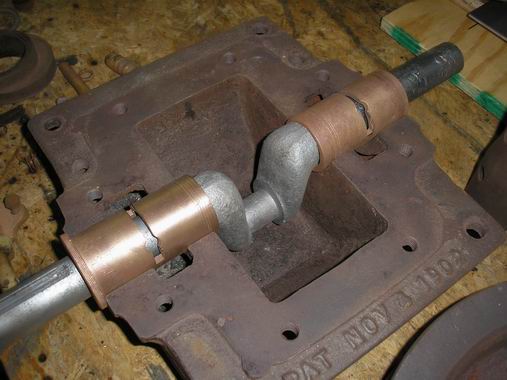
Have been looking at these photos again and like the way everything comes apart with the heat process,and how clean the parts are -can be put right in glass bead cabinet!
looking at that last photo the front bearing cleaned up so good I thought it was a newly made one at first!
 |
    
searcher
Senior Member
Username: searcher
Post Number: 138
Registered: 10-2004
| | Posted on Monday, September 04, 2006 - 11:14 am: | 


|
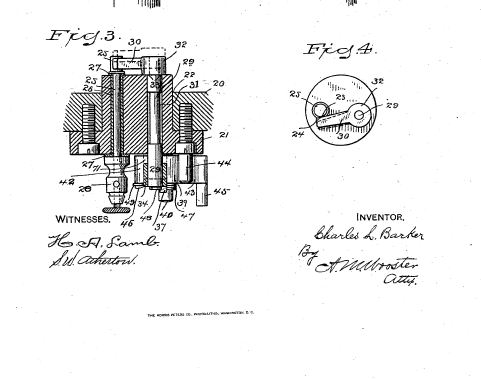
C. L. Barker was issued patent #745,474 on December 1, 1903 for the ignitor. I have attached screen captures of the two pages of drawings (had to do them in two sections each) but did not try to attach copies of the five pages of text he used to describe the function of the ignitor. The Patent Office scan was not very high resolution to begin with. By the time an image has been screen captured and then reduced below 50,000 pixels, the text is hard to read.
H.A. Lamb signed the document as one of the witnesses. Is this the same Lamb that shows up in other places associated with the design and manufacture of marine engines?

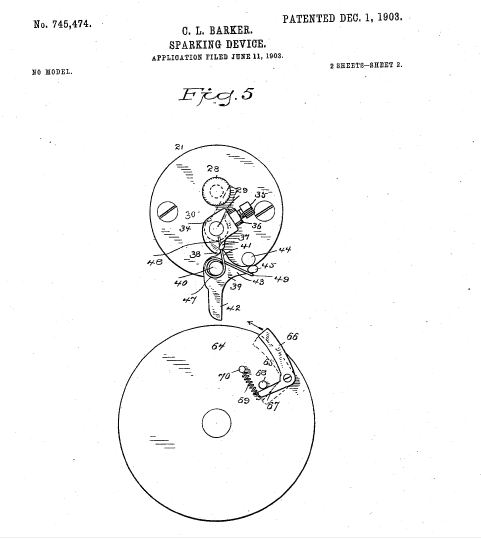
 |
    
robert
Senior Member
Username: robert
Post Number: 120
Registered: 07-2003
| | Posted on Monday, September 04, 2006 - 12:58 pm: | 


|
Here is a decent free batch photo resizer: www.FastStone.org
You will be costing yourself a lot of bandwidth with such huge photos. A third of their present size would be fine.
Very interesting, thank you for going to the trouble of documenting it for us. |
    
richarddurgee
Senior Member
Username: richarddurgee
Post Number: 1203
Registered: 11-2001

| | Posted on Monday, September 04, 2006 - 01:47 pm: | 


|
James Dwight Lamb founded the Lamb Boat and Engine Company in Clinton Iowa 1900. |
    
searcher
Senior Member
Username: searcher
Post Number: 140
Registered: 10-2004
| | Posted on Monday, September 11, 2006 - 04:43 pm: | 


|
George,
I was just perusing Barker's patent for the bearing support and also the photos you took of the parts after the first session in the furnace. As you and I got the engine, the collar on the bearing support was facing the pump eccentric. The patent drawings indicate that the collar should have been flipped 180 degrees. In that position, it seems to act as a spacer between the crank and the base/body of the engine (Patent drawing Fig. 1). I can see in one of your photos that you tried it both ways and that turning the collar inward also gives better alignment between the slot in the bearing support and the oil/grease reservoir. I cannot see if the other bearing support also has a collar. I can see a loose ring in one of your photos that may be the spacer for the other side of the crank.
Figure 3 of the patent drawings illustrates the metal rings (18) that rode loose on the crankshaft. They were loose but confined by the slots in the bearing support. The rings were supposed to carry oil from the reservoir to the crankshaft as they turned with the crankshaft. The patent description says the rings could be made of wicking material or metal rings with Barker preferring metal rings. I briefly poked around the grease in the reservoirs when I took the engine apart but I don't recall remnants of any such rings. Looks like the last person to work on the engine didn't pay attention to what went where and may have left some parts out. Maybe he simply slapped the engine back together without the intention of ever running it again. Who knows? |
    
george_iv
Advanced Member
Username: george_iv
Post Number: 47
Registered: 07-2003

| | Posted on Monday, September 11, 2006 - 10:07 pm: | 


|
Hello All,
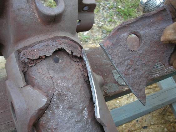
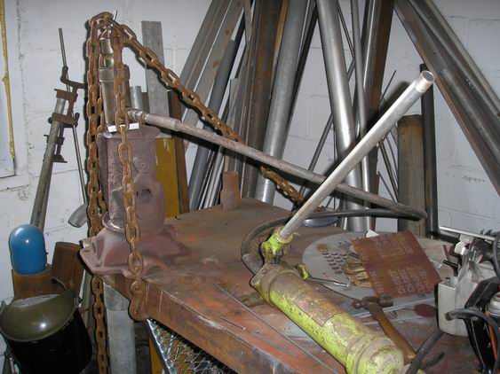
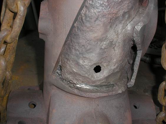
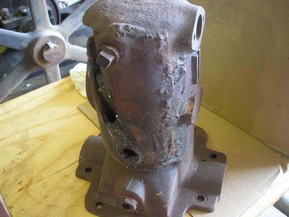
Just a few quick notes about the Barker. It has been through two heats now and the cylinder is cleaning up well. The water jacket is filled with some VERY hard concretions and I've had some trouble removing it from the hidden areas of the jug. I've also had to cut a part of the outer jacket away to gain access to cracks and a bad hole right behind the drain plug.
Keith - Well, I'd rather not share the smoke and mirror process of what I do; its taken some time to develop and most of it is a feeling or guess from experience. I would be horrified to learn that someone followed the process exactly and that they ruined an engine or piece. If you want something run through, let me know.
What I've found with the Barker is it is worn out, and has been before. I guess this engine has been rebuilt three time before. Yes, the mains have been put in backwards the last time. They have been replaced/redone once before I believe. The washer on the one brass is made of steel and shows signs of wear. I knocked it off the brass to see if the brass fit in the case in the correct orientation(washers to the crank). They do. There were no signs of the lube rings in the case after the heat. The brasses are severely worn from the lube rings which leads me to say they worked for a long time before being removed during the first rebuild. This system is similar to the Fairbanks-Morse stationary engine oiling system with rings that run in grooves through an oil reservoir. I think this design lends itself well to 2 cycle engines because of the limited oil available in the bearing to be sucked into the crankcase and cause engine run away. With a reservoir and no grease cups, the engine would require less maintenance. Just my guess.
I think the Barker ran a long time as built as a raw water cooled engine with minimal issues. After who knows how long, the Barker was rebuilt and the quality of that workmanship is lost to time. The fatal flaw... the thrust bearing at the tail was omitted. On the crankshaft and rear case there are signs of a standard washered thrust bearing wearing on them, but the shaft connector set screw marks on the crank for the first rebuild would place the connector tight against the case. With no thrust bearing the load would be taken by the forward crank cheek and the washer on the crank main bearing. I bet the engine didn't or wouldn't run a week without wearing the washer right off the main bearing shell. Hence the steel washer. To say the engine ran incredibly HOT for that week would be understated. At 140 deg f, the solids and salts in the raw water cooling any engine will precipitate out making the water jacket fill with solids at an alarming rate, making it run even hotter and so on.
Another rebuild by a not so qualified shop and it gets worse. Now the thrust washer is gone and forgotten, the mains are trashed and more probable than not the rod is worn along the sides where the crank has pushed it out of alignment. The mains were bored and babbit and grease fittings installed. The original oiling system is abandonded. The lack of thrust bearing is noted as a cause and the mains are turned where the washers can take the loads against the case. This proved fatal to the Barker. The crankshaft also bears the marks from the coupler spinning about 90 degrees where the set screws dug grooves. It probably ran OK for a long time before this happened but never ran great again. It also continued to run hotter and hotter. How's that for a CSI type guess!!
The washered thrust bearings for these engines are still available new from Aurora Bearings. Sit down when you ask how much, but I don't run without one, even on a engine outside the boat.
My fingers hurt...
Have a good evening.
George IVy |
    
searcher
Senior Member
Username: searcher
Post Number: 141
Registered: 10-2004
| | Posted on Tuesday, September 12, 2006 - 12:12 am: | 


|
George,
I am not surprised by your assessment of the poor little Barker. The Barker came from downeast Maine. Life in rural Maine was not easy for most of the last century, particularly in downeast Maine and in the western Maine mountains where I grew up in the fifties and sixties. It was a fact of life for many of us in those areas that if you didn't have something and you couldn't make it, grow it, or hunt it, you simply learned to get by without. The Barker was undoubtedly 'gumped up' a number of times by a subsistence fisherman who had little mechanical experience and even less economic means.
I will run down Aurora Bearings and see what damage will be. |
    
searcher
Senior Member
Username: searcher
Post Number: 142
Registered: 10-2004
| | Posted on Tuesday, September 12, 2006 - 12:38 am: | 


|
George,
Aurora Bearing was easy enough to find on the internet but typing 'thrust bearing' into Aurora's search engine produced nothing. What is the proper item to ask for? By the way, what is the diameter required for that bearing? |
    
george_iv
Advanced Member
Username: george_iv
Post Number: 48
Registered: 07-2003

| | Posted on Tuesday, September 12, 2006 - 01:19 pm: | 


|
Oopse, I made a mistake. It's www.auburnbearing.com and look for the T-100 style. The shaft is 1 1/4. McMaster happens to have your size for about $20.00 instead from Auburn for about $100.00.
GIVy |
    
george_iv
Advanced Member
Username: george_iv
Post Number: 49
Registered: 07-2003

| | Posted on Tuesday, September 19, 2006 - 06:28 pm: | 


|
OK All,
More news and pictures are up.
http://www.ghcoates.com/Barker.htm
George IVy |
    
searcher
Senior Member
Username: searcher
Post Number: 143
Registered: 10-2004
| | Posted on Tuesday, September 19, 2006 - 09:35 pm: | 


|
George,
What kind of insulation are you using around the engine being welded? |
    
george_iv
Advanced Member
Username: george_iv
Post Number: 50
Registered: 07-2003

| | Posted on Tuesday, September 19, 2006 - 09:58 pm: | 


|
The white fluffy kind, of course! It is a kind of extreme temerature ceramic fiber that is used sometimes in furnace combustion chambers, the name of which escapes me now. We have had this bundle forever it seems. |
    
searcher
Senior Member
Username: searcher
Post Number: 146
Registered: 10-2004
| | Posted on Sunday, September 24, 2006 - 04:06 pm: | 


|
George,
I went on the hunt for thrust bearings to fit the Barker hoping to find something that would be in keeping with the original appearance. I checked Auburn Ball Bearing and McMaster-Carr as you suggested and others as well.
McMaster-Carr has an interesting bronze thrust bearing that has imbedded graphite plugs. Apparently, the graphite plugs wear down at the same rate as the bronze thus keeping the bearing surfaces lubricated without the need for grease. By putting a bronze washer on each side of one of these thrust bearings, the appearance approximates the three piece type of the thrust bearing I am used to seeing on these old engines. However, the total thickness of the three pieces is only 3/8" and the thickness of the typical three piece antique thrust bearing is 5/8". Adding one more washer and one more graphite plugged thrust bearing brings the total thickness to 5/8".
Auburn Ball Bearing offers the T-100 you mentioned. That bearing comes as an assembled unit rather than the loose hardened steel washers and the bronze plate with ball bearings typical of the antique thrust bearings I have seen. However, the Auburn bearing does come in a thickness consistent with the old bearings and can be had with a brass outer band that would help from an appearance standpoint.
At this point, I was still operating under the assumption that all the antique thrust bearings were the loose three piece type. Quite by serendipity, I was flipping through a 1909 issue of Motorboat. Lo and behold, there was a thrust bearing that came as an assembled unit similar to the Auburn bearing. So, now there were two options that reasonably approximated the antique thrust bearings.
Hard to tell sight unseen which of the two might look the best on an antique engine so I ordered a set from each company.

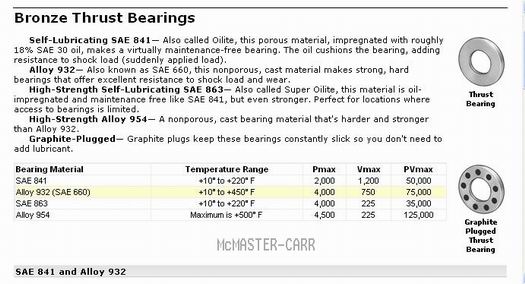
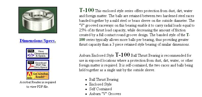 |
    
searcher
Senior Member
Username: searcher
Post Number: 153
Registered: 10-2004
| | Posted on Tuesday, October 03, 2006 - 12:13 am: | 


|
Auburn informs me they no longer supply the
T-100 with the brass band. Too bad, it would have been a relatively inexpensive way to go.
Auburn's AE series are the three piece style consisting of roller bearings in a bronze cage with a hardened steel race on each side. The AE series are also the same thickness (5/8") as the old style three piece bearing. The AE series seem to be the closest in outward appearance to the old style bearing (assuming the bearings themselves are not visible). George was right about price, they spoil $116 by the time you pay shipping. Hey, this is a fun exercise and life is short. So, the little Barker is going to get a first class AE-24 bearing.
 |
    
searcher
Senior Member
Username: searcher
Post Number: 154
Registered: 10-2004
| | Posted on Tuesday, October 03, 2006 - 12:31 am: | 


|
The attached photo came from a Barker catalog that probably dates from about 1920 give or take three or four years. Note the unusual oil reservoir. The piping that carries the oil from the reservoir to the front bearing is also visible. There is a little rod sticking up through the cover of the oil reservoir. I am assuming that pressing on that little rod occasionally released oil to the individual bearing reservoirs.
George, what do I need to be looking for as regards the rings that run on the crankshaft in the oil reservoirs?
The same 1920 catalog illustrates the Barkers as using Schebler D carburetors. I think this little Barker may date before 1910 and may or may not have used a Schebler. Does anyone have an early illustration or photo of an early Barker engine with the carburetor on it?
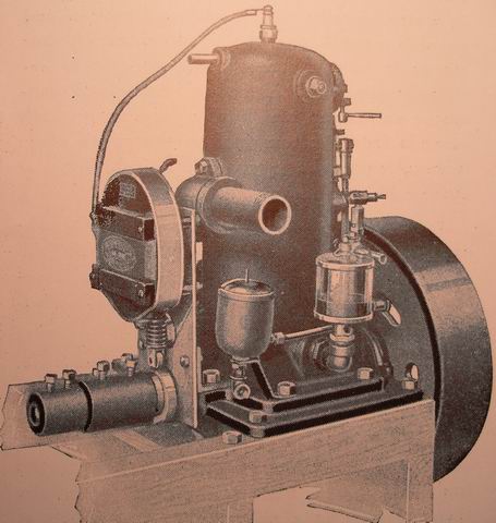 |
    
richarddurgee
Senior Member
Username: richarddurgee
Post Number: 1310
Registered: 11-2001

| | Posted on Tuesday, November 07, 2006 - 06:57 am: | 


|
*
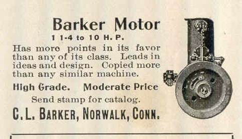
Barker ad 1905
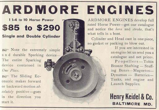
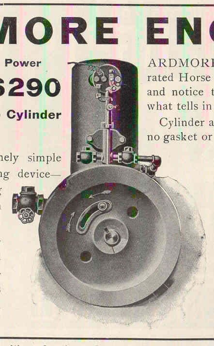
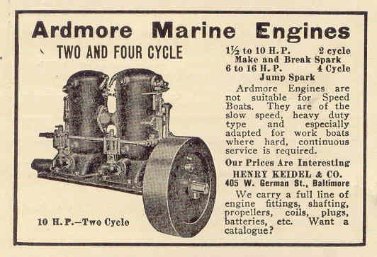
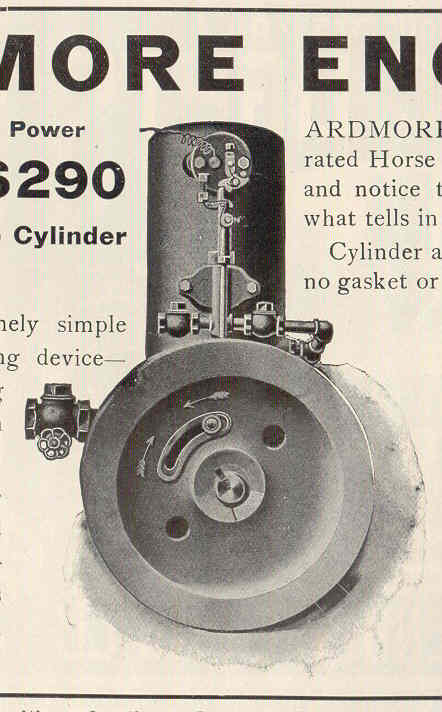
Around 1904-05 Henry Keidel & Company of Baltimore, Md. Began advertising The "ARDMORE ENGINES" ????
 |
    
searcher
Senior Member
Username: searcher
Post Number: 159
Registered: 10-2004
| | Posted on Tuesday, November 07, 2006 - 11:59 pm: | 


|
Thanks for posting the Ardmore ad. The plates used to print the illustration of the motor in the Barker and Ardmore ads appears to have been etched from the same photo. |
    
searcher
Senior Member
Username: searcher
Post Number: 185
Registered: 10-2004
| | Posted on Tuesday, March 27, 2007 - 08:32 pm: | 


|
Whether by chance or design, the November 1909 issue of The Rudder carried the Barker and Ardmore ads one immediately above the other.
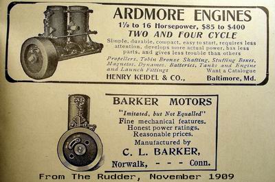 |
    
searcher
Senior Member
Username: searcher
Post Number: 186
Registered: 10-2004
| | Posted on Tuesday, March 27, 2007 - 08:32 pm: | 


|
Whether by chance or design, the November 1909 issue of The Rudder carried the Barker and Ardmore ads one immediately above the other.
|
    
george_iv
Senior Member
Username: george_iv
Post Number: 62
Registered: 07-2003

| | Posted on Thursday, February 21, 2008 - 11:28 am: | 


|
Hello All - Just a note to say I've posted 3 new pictures of the Barker progress. It's been slow, but it is still moving forward. We haven't pressure tested the bore, but I am going to say all the real hard work is done on the inside water jacket. It still needs the exterior water jacket done, but that's all exposed work and easy to get to with the torch.
More to come...
George IVy
http://www.ghcoates.com/Barker.htm |
    
jb_castagnos
Senior Member
Username: jb_castagnos
Post Number: 332
Registered: 07-2002

| | Posted on Thursday, February 21, 2008 - 10:00 pm: | 


|
Thanks for the update George, hope to see it at Calvert. |
    
george_iv
Senior Member
Username: george_iv
Post Number: 65
Registered: 07-2003

| | Posted on Wednesday, June 18, 2008 - 10:32 am: | 


|
More updates...
The outer jacket is as done as we can make it and now the missing piece needs to be cast. It'll be cast iron from a pattern made from the existing hole in the water jacket. That way its guaranteed to fit and look right. If anyone has any more drawings, or pictures of this side that shows features, or bosses that are missing, now would be a great time post them. Its easier to include the features and bosses now in the casting than to put them on later.
Here are more new pictures.
http://www.ghcoates.com/Barker.htm
Enjoy,
George IVy |
    
ernie
Senior Member
Username: ernie
Post Number: 832
Registered: 01-2002

| | Posted on Wednesday, June 18, 2008 - 11:02 am: | 


|
Neat! |
    
searcher
Senior Member
Username: searcher
Post Number: 241
Registered: 10-2004
| | Posted on Wednesday, June 18, 2008 - 11:28 am: | 


|
George,
Hard to believe the old girl is being resurrected, neat stuff.
I have the connecting rod for the Barker but need to have the bottom bearing cap made. It shouldn't be too big a deal but it is bronze and my muffle will only go to about 2000 degrees. So I will make a pattern and have a local bell founder cast it.
I did not get a piston with the Barker. Let me know what the required size is and I will try to find one that is close.
I bought thrust bearings for the Barker and can send them down to you or bring them to Mystic.
The attached profile of a Barker engine came from their catalog N. It is the only illustration from the catalog that gives a hint as to what that side of the engine looked like. This profile indicates there are no bosses in that area. The catalog isn't dated but I suspect it is from the 1921-1924 period so it is much later than the engine you are working on. Given that Barker didn't seem to change things much, the profile illustration is probably applicable to this Barker.
Are you going to show the progress at Mystic?
 |
    
searcher
Senior Member
Username: searcher
Post Number: 242
Registered: 10-2004
| | Posted on Wednesday, June 18, 2008 - 11:36 am: | 


|
I take that back - senior moment. My post 154 also shows that side of the Barker and there is a boss for the cooling water discharge on that side. Maybe that got shifted there from the earlier versions. |
    
jb_castagnos
Senior Member
Username: jb_castagnos
Post Number: 373
Registered: 07-2002

| | Posted on Wednesday, June 18, 2008 - 01:42 pm: | 


|
I have patterns for 3 1/2 & 4" pistons, I have a 4" casting in alluminum. |
    
george_iv
Senior Member
Username: george_iv
Post Number: 66
Registered: 07-2003

| | Posted on Wednesday, June 18, 2008 - 01:47 pm: | 


|
Mr. Day,
Isn't that mixer similar to the early Palmer mixer?
George IVy |
    
searcher
Senior Member
Username: searcher
Post Number: 243
Registered: 10-2004
| | Posted on Wednesday, June 18, 2008 - 02:22 pm: | 


|
J.B.,
I have two 3" dia. cast iron 2 cycle pistons that have the same ring pattern as that shown on the Barker above. If those pistons are too small, I will get back with you and see if your patterns are the right size and if so see about having a piston made up. Thanks. |
    
george_iv
Senior Member
Username: george_iv
Post Number: 67
Registered: 07-2003

| | Posted on Wednesday, June 18, 2008 - 03:24 pm: | 


|
Fellows,
Right now the bore is 4 1/8. If we need to sleeve it, I'll probably recommend going to 4 inches. It seems to be easier to find pistons in that size range.
George IV |
    
richarddurgee
Senior Member
Username: richarddurgee
Post Number: 1722
Registered: 11-2001
| | Posted on Wednesday, June 18, 2008 - 03:55 pm: | 


|
*
Close but not a match !
1905 Barker\Ardmore mixer
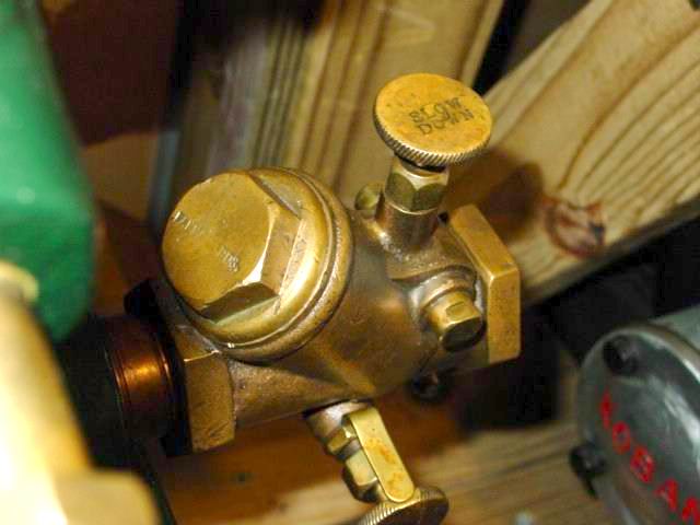
1906 Palmer mixer
* |
    
richardday
Senior Member
Username: richardday
Post Number: 620
Registered: 11-2003

| | Posted on Wednesday, June 18, 2008 - 05:32 pm: | 


|
George, It is close but Richard's photo shows the Palmer mixer. I am surprised more people didn't go the same route making mixers. Just take a basic swing check and bore a hole on the valve add the needle valve seat and you are home essentially free. Palmer put the "Slow Down" control to limit the lift on the valve. This functioned as a throttle. Not seen in this picture is a rod out the bottom to the right which allows one to unstick the valve off the seat if it gets stuck. Not sure how/if the Barker mixer is throttled. I believe the Palmer mixer went out of production about 1907. By that time Palmer was using Schebler Model D and indicated others could be supplied at customer request. They indicated they preferred the Model D over other makers on their models C,D and E two strokes. With the sucess of the float feed carburetors like Krice, Monarch, Generator Valve Co. etc. I expect the mixing valve with its leaking problem went the way of the gooney bird in small boat marine engines. I have experienced some Schebler model Ds which don't drip gas when running and more that do. I think Ernie with the Viton tip is a clear winner in that regard. Driping gas at a show is bad enough but intolerable in a boat. As a kid I remember most carburetors had a brass, rectangular can with a tight fitting fine mesh brass screen cover hung under every carburetor to catch any drips. |
    
richardday
Senior Member
Username: richardday
Post Number: 621
Registered: 11-2003

| | Posted on Wednesday, June 18, 2008 - 05:36 pm: | 


|
OOPS I should have said bore a hole on the valve SEAT!!! |
    
kerrigan
New member
Username: kerrigan
Post Number: 1
Registered: 06-2008
| | Posted on Wednesday, June 18, 2008 - 07:12 pm: | 


|
The photo in searcher's post 241 shows the image of one side of the Barker piston assembly and the opposite side of the cylinder assembly. One assembly must be rotated to line up the flange bolts |
    
jb_castagnos
Senior Member
Username: jb_castagnos
Post Number: 374
Registered: 07-2002

| | Posted on Thursday, June 19, 2008 - 08:12 am: | 


|
That's an artist drawing, it may not be totally correct but the ignitor is facing the flywheel and the deflector is way from the exhaust. It looks right to me. |
    
george_iv
Senior Member
Username: george_iv
Post Number: 68
Registered: 07-2003

| | Posted on Wednesday, December 17, 2008 - 12:02 pm: | 


|
Great News!!!
The pieces are back from the foundry and we'll have the water jacket completed soon! The little Barker is shaping up nicely.
Merry Christmas and Happy New Year to All!!
George IV
http://www.ghcoates.com/Barker.htm |
    
searcher
Senior Member
Username: searcher
Post Number: 268
Registered: 10-2004
| | Posted on Tuesday, December 23, 2008 - 10:37 pm: | 


|
George,
JB has a used 4" LA iron piston and a new 4" aluminum piston that hasn't been machined yet. There may be some advantage in the aluminum piston in that the hole for the pin has not been machined yet. I asked JB to send both to you for the fitting.
I'm working on getting that connecting rod bearing cap made. I will then send that assembly along.
I have two styles of new thrust bearings for the Barker. One set is the standard three piece and is 2 3/8" outside diameter. The other set is made up of five pieces and is 2" in diameter. Which set is the closest in diameter to the coupling?
I just missed a generator valve that is close in appearance to the one shown in a Barker ad posted earlier in this thread by Richard Durgee (June 18, 2008). It would be terrific if someone on this board had one similar they would be willing to sell for this project. Otherwise, I will send a Lunkenheimer 1" non-pareil Model C generator valve to put on it.
If you go back to my October 3, 2006 post of an engine taken from a c1920 Barker catalog, you will see what I think is a fuel float valve (In my total ignorance of such things at the time, I thought it was an oiling arrangement). If that is a float valve, why would Barker put on that side of the engine and then use a line all the way around the front of the engine to get to the generator valve?
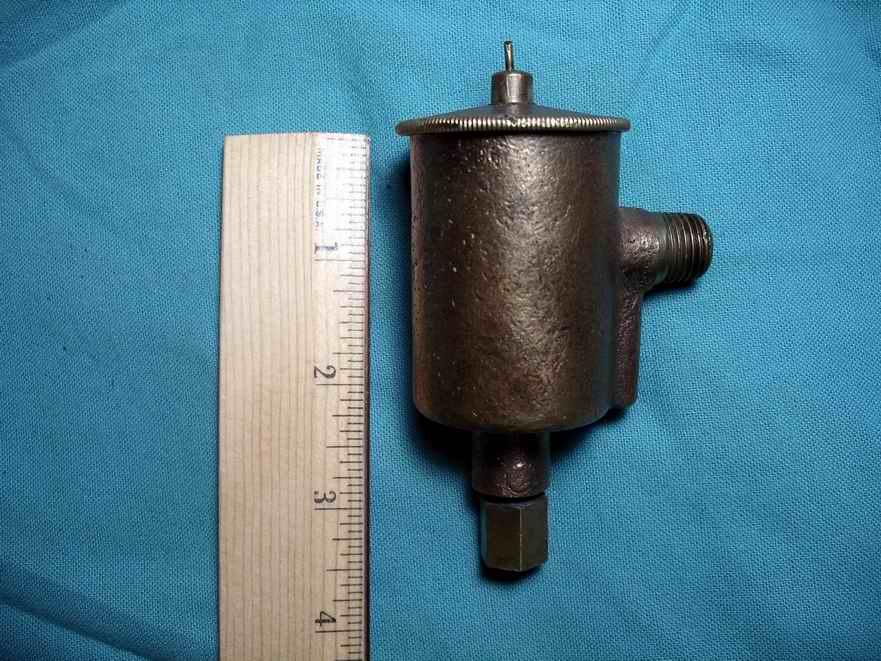
I did find a float chamber but it is a little smaller than would be ideal for the Barker (see attached photo. However, if the consensus of this board is to use it, I will send that along to you as well.
I think the oil cup depicted on the Barker is a Michigan Lubricator. I just gave the Maine Antique Power Association my only vent tube and checkball Michigan to use on an engine for the clubs annual fund raising raffle. I will send along a nice National Brass #2 or Lavigne #2 for the Barker unless I find a #2 Michigan in the meantime.
The Barker had two Williams check valves on it when I got it and I will send those down in the package along with the rest of the brass fittings for the cooling system. The check valves don't have a wrench mark on them, a surprise considering the condition of the rest of the engine. They must have been replacements installed just before the engine was retired.
I never dreamed that the new cast pieces you've just posted would look so good or fit so well.
 |
    
searcher
Senior Member
Username: searcher
Post Number: 269
Registered: 10-2004
| | Posted on Thursday, December 25, 2008 - 12:14 am: | 


|
George,
Here is a photo of what I have believed to be the connecting rod for the Barker. While I was working up a form for the bearing cap, it dawned on me that the rod was short and small for a 2 1/2 hp engine. Before I get the bearing cap cast, would you check to see if the dimensions I show in the photo are consistent with the Barker. I would expecially like to know the diameter of the crankshaft journal. The crank end of the connecting rod I have would fit a 1" diameter journal. Thanks.
 |
    
george_iv
Senior Member
Username: george_iv
Post Number: 70
Registered: 07-2003

| | Posted on Monday, December 29, 2008 - 03:11 pm: | 


|
Hello Everybody!
From VERY QUICK calculations, the piston will need to be 4 1/16 to 4 1/8 diameter and 5 inches long. It will probably need the ring on the bottom of the skirt. The dark secret here is the transfer ports and exhaust ports are in line with the crank. Therefore, the pin must ride above the top of the port and still be below the second compression ring. And not interfere with the skirt at midstroke... Quite a bit to think about. I'm happy to take a look at JB's pistons, but it might be better to get the rest of the math done on the piston and connecting rod first.
The connecting rod will probably be a short, stout unit not more than 6 inches long. Let's hold on the connecting rod cap project until I see where the crank finishes.
The coupling is just over 2 inches in diameter.
More to follow!! Have a great New Year!!
George IV |
    
jb_castagnos
Senior Member
Username: jb_castagnos
Post Number: 425
Registered: 07-2002

| | Posted on Monday, December 29, 2008 - 08:41 pm: | 


|
The castings will clear 4 1/8", but I think the one I have has been rough turned below that. The deflector on these is parallel to the pin, on the aluminum it could be cut and a new one welded on. I could also send the pattern and core box if you have someone to cast them, the core could be rotated to pour the piston correctly, pin boss could be slotted to allow movement. For a one time piston you may want to consider machining from a piece of round stock, that's what I have in the Fisherman. |
    
george_iv
Senior Member
Username: george_iv
Post Number: 77
Registered: 07-2003

| | Posted on Friday, September 25, 2009 - 11:58 am: | 


|
Hey Guys!
New Stuff on the Barker.
http://www.ghcoates.com/Barker.htm
If someone wants to take the pictures and resize to post here, feel free to do so.
George |
    
richardday
Senior Member
Username: richardday
Post Number: 811
Registered: 11-2003

| | Posted on Friday, September 25, 2009 - 03:35 pm: | 


|
Bravo, What a well done job. Took a lot of guts to take on that challenge. |
    
kerrigan
Member
Username: kerrigan
Post Number: 23
Registered: 06-2008

| | Posted on Saturday, September 26, 2009 - 09:15 pm: | 


|
Bob Holcomb's June 13th 2006 remarks on the subject of saltwater corrosion are interesting, especially this: "i know the salt is a preserative and what affects the cast iron is the rest of the salt water chemicles." Two samples of sea water are highly unlikely have the same analyses even when taken at the same location at different intervals. Therefore it seems logical that engines cooled in atlantic water and let to dry will suffer greater or lesser problems than those operated in other bodies of water. Richard Day is almost fanatical about not letting salt water cooled engine jackets dry out. He has much experience over a period of many years. I can't help wondering if all or most of that experience is with that Damn Yankee water and it's particular chemicals and if the water in the Gulf of Mexico, Galveston Bay for instance, which has fresh water run off from a huge area, will be more or less corrosive. I'm attempting to justify my not giving my engine cylinder the heat treatment before having it sleeved. . . now it's too late. Any sympathizers? |
    
robert
Senior Member
Username: robert
Post Number: 300
Registered: 07-2003
| | Posted on Saturday, September 26, 2009 - 10:48 pm: | 


|
George, amazing work. Just goes to prove there is no engine "beyond repair". As for photos, you must be costing yourself a lot of bandwidth with those huge images. Try FastStone Photoresizer, www.faststone.org, it's a free download and I've used it with no problems at all. No registration or other tiresome catches either! ;-) |
    
jb_castagnos
Senior Member
Username: jb_castagnos
Post Number: 475
Registered: 07-2002

| | Posted on Sunday, September 27, 2009 - 04:58 pm: | 


|
I got to see it "hands on" and it's even better than the pictures. From what I've heard they aren't too far away from making compression. |
    
jb_castagnos
Senior Member
Username: jb_castagnos
Post Number: 480
Registered: 07-2002

| | Posted on Tuesday, September 29, 2009 - 09:04 pm: | 


|
They have added some more pics, maybe someone could reduce them and post them here. |
    
george_iv
Senior Member
Username: george_iv
Post Number: 78
Registered: 07-2003

| | Posted on Wednesday, September 30, 2009 - 09:01 am: | 


|
Sorry about the pictues. I thought they had all uploaded when I posted last time. They are there now.
I will start the rod this week and hope to make compression by the end of next week. We will mount the Barker on a rough base just for testing and spin it for timing and assembly purposes.
Searcher, if you would begin forwarding the last of the parts you have we'll be ready for them.
George |
    
searcher
Senior Member
Username: searcher
Post Number: 347
Registered: 10-2004
| | Posted on Thursday, October 01, 2009 - 01:00 am: | 


|
George,
I will send you the following shortly:
A. Plumbing cleaned up, repaired, and assembled
B. Two oil cups with brass pipe
C. Two grease cups with brass pipe and elbows
D. Grounding screw
E. Generator valve or carburetor
F. Thrust bearings
If I missed something, let me know.
What is the thread size of the two openings for the oil cups?
What is the thread size of the two openings for grease cups?
Which generator valve or carburetor would seem to be the best choice?
Which set of thrust bearings would look better, the 2 5/16" wide ones or the 2" wide ones?
I found the screw for the ground wire in the box - neat!


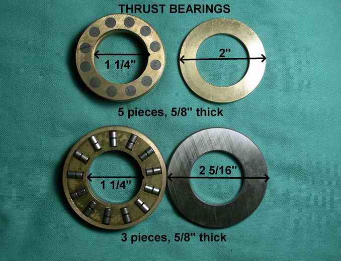 |
    
searcher
Senior Member
Username: searcher
Post Number: 348
Registered: 10-2004
| | Posted on Thursday, October 01, 2009 - 07:03 am: | 


|
George,
If that is a 2 port, which I think it is, I will also need to send you a check valve if you choose a carburetor. A check valve is not required if you think a generator valve is best. What is the pipe size of the opening into the crankcase? |
    
ernie
Senior Member
Username: ernie
Post Number: 1061
Registered: 01-2002

| | Posted on Thursday, October 01, 2009 - 08:10 am: | 


|
I had one of these many years ago and it seemed quite original. It had a Schebler and check valve.
Hope this helps
Ernie |
    
george_iv
Senior Member
Username: george_iv
Post Number: 79
Registered: 07-2003

| | Posted on Friday, October 02, 2009 - 08:18 am: | 


|
Searcher,
The oiler for the crank case is 3/8 NPT. Which ever generator you would like to have on is fine. We'll get it running with a known good dribbler carb and check and then put the generator on for a final tuning. The oil gallery's are plugged with a brass knurled bolt, so nothing needed there. The two checks for the water pump would be good to have. The 3 piece thrust bearing would be fine.
Soon she'll be ready for that North Atlantic crossing!
George |
    
searcher
Senior Member
Username: searcher
Post Number: 349
Registered: 10-2004
| | Posted on Friday, October 02, 2009 - 02:07 pm: | 


|
George,
Photos A and B show the original plumbing as it came off the engine. I'm going to refurbish the plumbing this weekend and send it all down with the other stuff. For whatever reason, the plumbing on this one was set up just reverse of the Barker in the catalog (PhotoE) and a restored Barker (Photo C and D) posted on OME some time ago. As long as there are openings into the crankcase on each side, and the checkvalves are in the right orientation, it
doesn't make any difference that I can see. Anyway, I will send you all the pieces and you can screw them together for whichever side works.
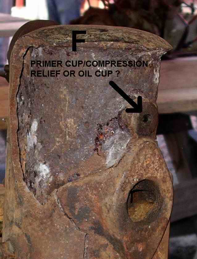
Photo F shows an opening into the cylinder. Was that opening for a tricock or a primer cup? I can send either, just let me know which and the
thread size. The restored engine in Photo D used a tricock but I don't know the basis for using it as opposed to using a primer cup.
In Photo G, I assume this is where you would place the oil cup? This Barker seems to predate the practice of mixing oil in the gas. If that is true, there would also have been an oil cup for the cylinder. You mentioned that the oil galleries are plugged with a brass knurled bolt. Was that a factory plug or was it done sometime later? I can't think of where it would be. Does it plug galleries for oil or for grease?
I can see in my photos of the Barker that there are threaded holes fore and aft for grease cups. The restored Barker in Photo D has t-handle grease cups. I doubt if Barker used anything that nice as the Barker engines seem
to be bare bones in concept and execution. (Which probably explains why Barker was still making and selling plain Jane marine engines long after 90% of the other marine engine manufacturers had gone out of the business). So, I am sending a pair of matching, but rather ordinary, brass grease cups which would seem to be more in keeping with the Barker concept (unless these are the galleries you refer to and the cups are not needed).
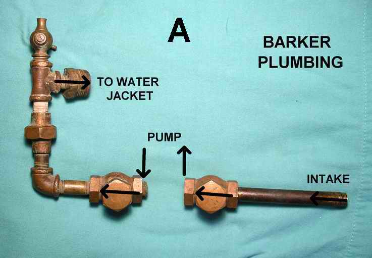

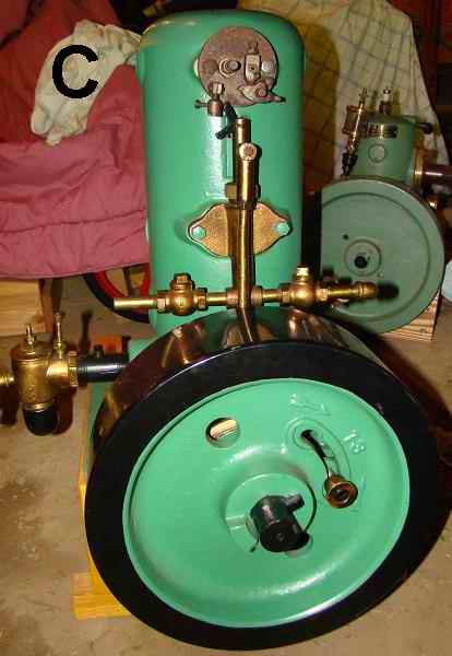
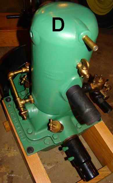

 |
    
richarddurgee
Senior Member
Username: richarddurgee
Post Number: 2191
Registered: 11-2001
| | Posted on Friday, October 02, 2009 - 10:09 pm: | 


|
*
Sept 14 2006
-
Sept 15 2006 1 and 1a
-
Sept 19 2006 1, 1a and 1b}
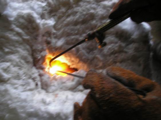
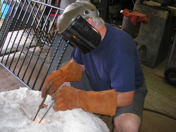
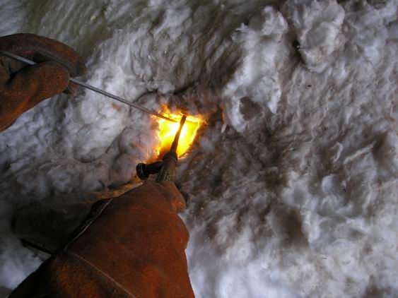
-
Sept 20 2006 1, 1a and 1b
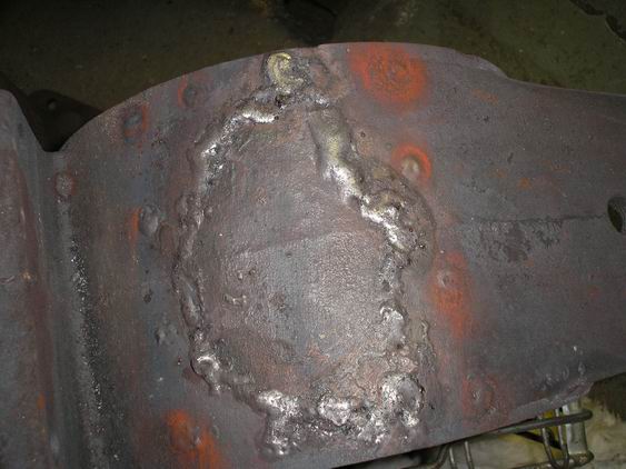
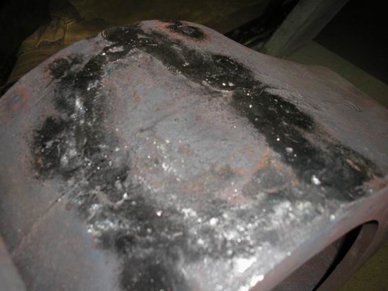
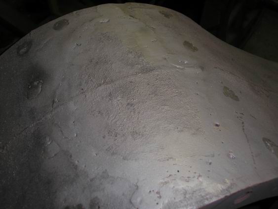
-
Feb 21 2008 1, 1a and 1b
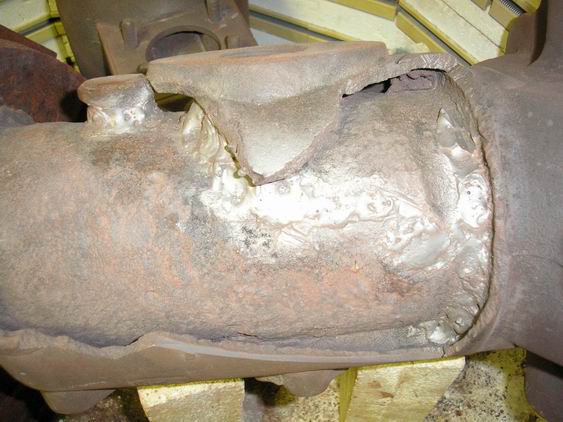
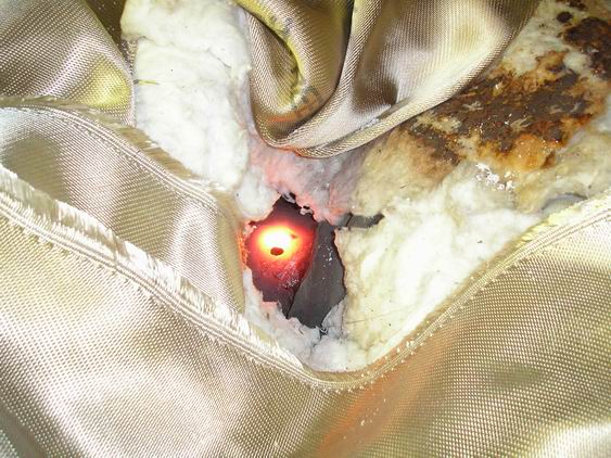
I'll continue to work on posting the rest of these photos !! |
    
richarddurgee
Senior Member
Username: richarddurgee
Post Number: 2192
Registered: 11-2001
| | Posted on Saturday, October 03, 2009 - 08:42 am: | 


|
*
June 2008 photos, two of these would not open ?
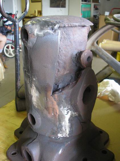
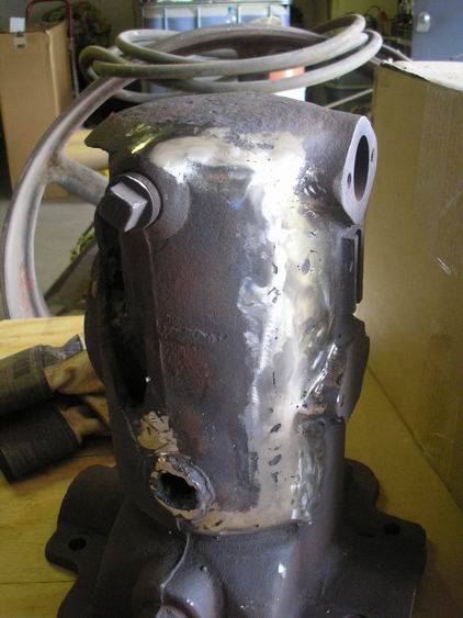
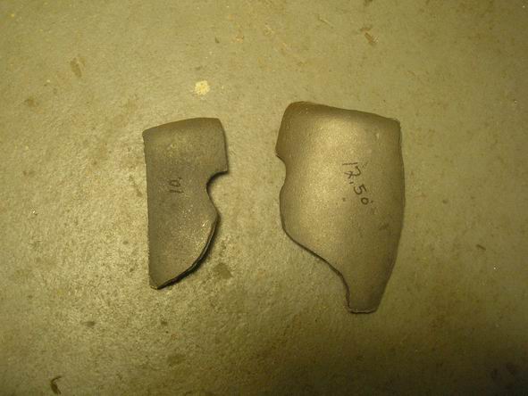
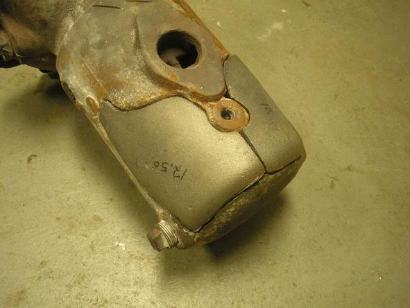
* |
    
richarddurgee
Senior Member
Username: richarddurgee
Post Number: 2193
Registered: 11-2001
| | Posted on Saturday, October 03, 2009 - 09:12 am: | 


|
*
September 25 2009
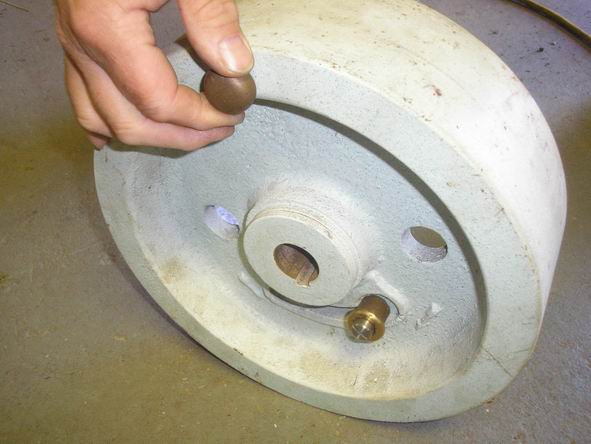
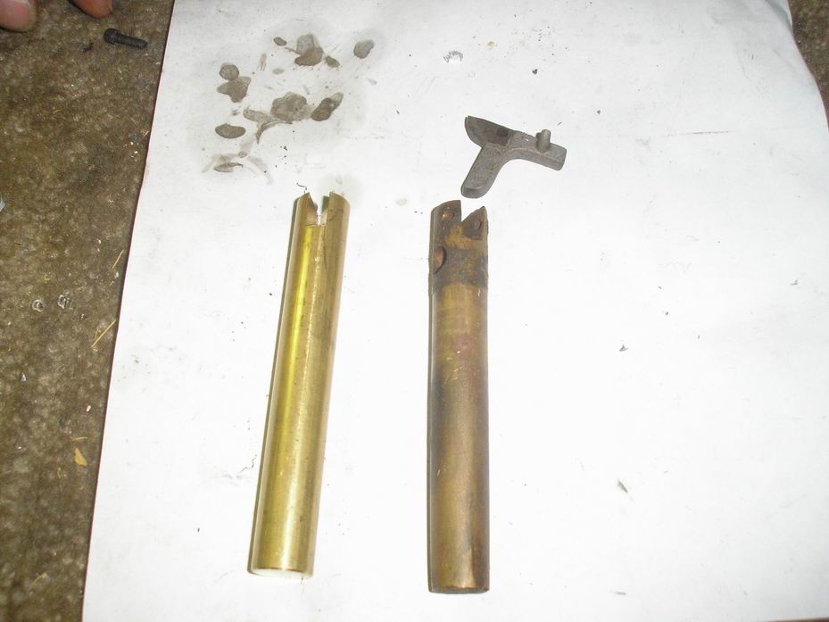
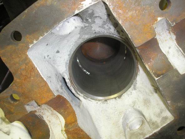
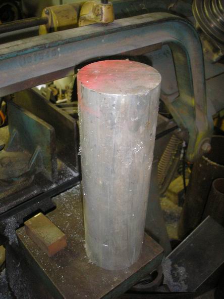
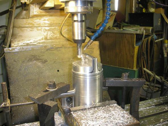
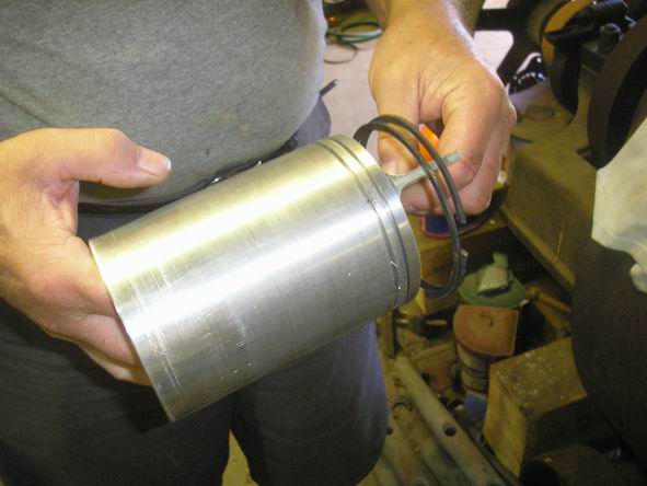
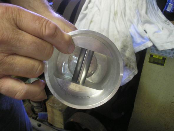
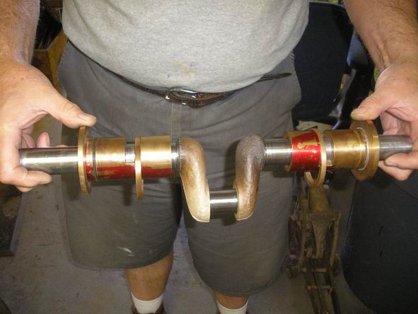
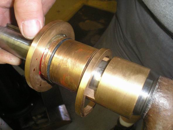
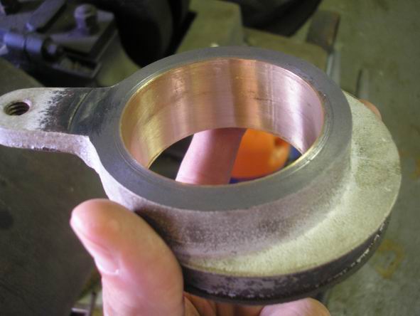
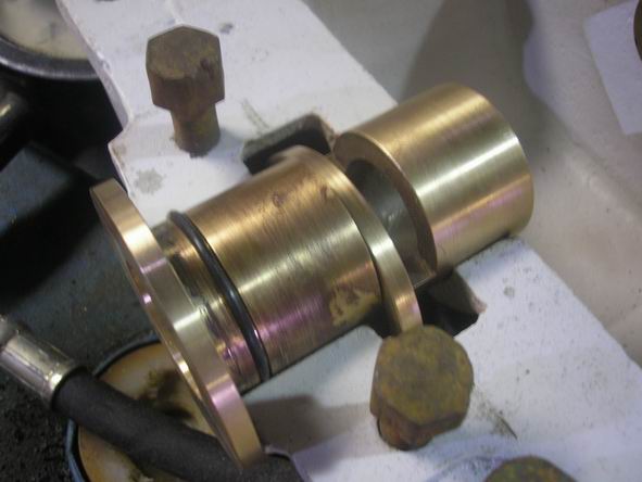
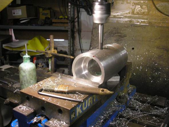
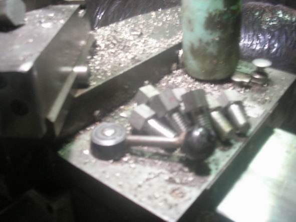
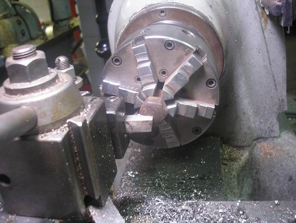
------
October 1 2009
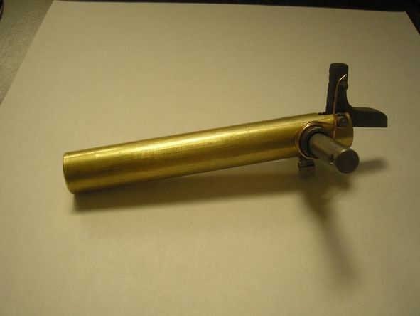
** |
    
jb_castagnos
Senior Member
Username: jb_castagnos
Post Number: 482
Registered: 07-2002

| | Posted on Saturday, October 03, 2009 - 08:39 pm: | 


|
Thanks for taking the time to reduce and post the pictures Richard, they were slow loading, this makes it easy to view them. |
    
kerrigan
Member
Username: kerrigan
Post Number: 24
Registered: 06-2008

| | Posted on Saturday, October 03, 2009 - 09:24 pm: | 


|
How was the thickness of the oil rings determined? They look thicker than I have seen on other modern rotating equipment. |
    
searcher
Senior Member
Username: searcher
Post Number: 350
Registered: 10-2004
| | Posted on Sunday, October 04, 2009 - 05:26 pm: | 


|
George,
I may have to send along two Lunkenheimer Marine #2 instead of plain jane grease cups. It depends on the pipe thread size of the holes on the engine. Could you let me know and I will either make up something or send the Lunkenheimers. |
    
george_iv
Senior Member
Username: george_iv
Post Number: 80
Registered: 07-2003

| | Posted on Sunday, October 04, 2009 - 06:59 pm: | 


|
Kerrigan,
The oil rings were a best guess based on the original brasses, and the patent drawings. We added the orings and lip seals as a measure to reduce the blow by on the crank.
Searcher,
The grease cup holes have been filled, so don't worry about the cups. We looked at the ads and think the grease cups were added after the fact. They were on opposite sides, and placed so grease would have just gone into the oil reservoir instead of the bearing.
George |
    
ernie
Senior Member
Username: ernie
Post Number: 1062
Registered: 01-2002

| | Posted on Sunday, October 04, 2009 - 07:26 pm: | 


|
George,
Correct there should NOT be any grease cups.
Twice I had the one I had apart fairly soon after it had been run and the mains were quite oily.
By the way NICE work
Ernie |
    
searcher
Senior Member
Username: searcher
Post Number: 351
Registered: 10-2004
| | Posted on Sunday, October 04, 2009 - 08:42 pm: | 


|
I am a little puzzled about the grease cups. The c. 1920 cut below of the 2 cylinder Barker clearly shows grease cups and they are on opposite sides just as they are on this Barker as George pointed out. Note the 2 cylinder Barker used two Scheblers or Schebler knockoffs.
The generator valve I chose to send for this Barker is the Monarch. The Barker stationary in the cut clearly shows a Monarch like this one so we know the Monarch was used by Barker. I have included an April 1905 Rudder ad depicting this identical generator valve.
Barker Stationary, Barker Catalog c. 1919
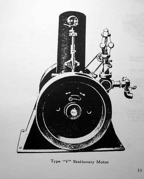
Monarch ad in Rudder, April 1905
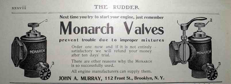
Barker 2 cylinder, Barker Catalog, c.1921
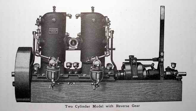 |
    
ernie
Senior Member
Username: ernie
Post Number: 1063
Registered: 01-2002

| | Posted on Sunday, October 04, 2009 - 09:10 pm: | 


|
There was a Barker stationary like the cut you posted above at the 1st Mystic show. I think it was from the CT Antique Machinery Assn in Kent CT
www.ctamachinery.com
The hours they are open are on the above web page
I know the one I had (like yours) didn't have grease cups as one of the oil resivours leaked and I had to take the engine apart to repair it. I suspect it had been full of water at one time then frozen and cracked.
Maybe everything but the small singles had grease cups.
Hope this helps
Ernie |
    
kerrigan
Member
Username: kerrigan
Post Number: 25
Registered: 06-2008

| | Posted on Sunday, October 04, 2009 - 10:06 pm: | 


|
Thanks George,
I don't wish to be an alarmist but my concern is the oil rings may be too heavy to rotate. There weren't no magic engineering to oil ring sizing at the pump company where I was employed. They were generally cut from whatever copper pipe was available. They must turn to splash oil for cooling and lubrication. A simple test set-up using a piece of round stock the size of the engine shaft chucked in your lathe with a ring installed and an oil pan underneath may be a worthwhile investment. Start slow so you don't splash oil around your shop.
Spence |
    
richarddurgee
Senior Member
Username: richarddurgee
Post Number: 2199
Registered: 11-2001
| | Posted on Monday, October 05, 2009 - 10:02 pm: | 


|
*
1907
** |
    
searcher
Senior Member
Username: searcher
Post Number: 355
Registered: 10-2004
| | Posted on Tuesday, October 13, 2009 - 01:51 am: | 


|
George,
Here are the bits and pieces to dress up the Barker. I will also include the thrust bearings and the grounding screw in the box as well. I also will put in a couple of pieces of polished 1/4" pipe to make up the pieces to get from the check valves to the pump. Let me know if I missed something.
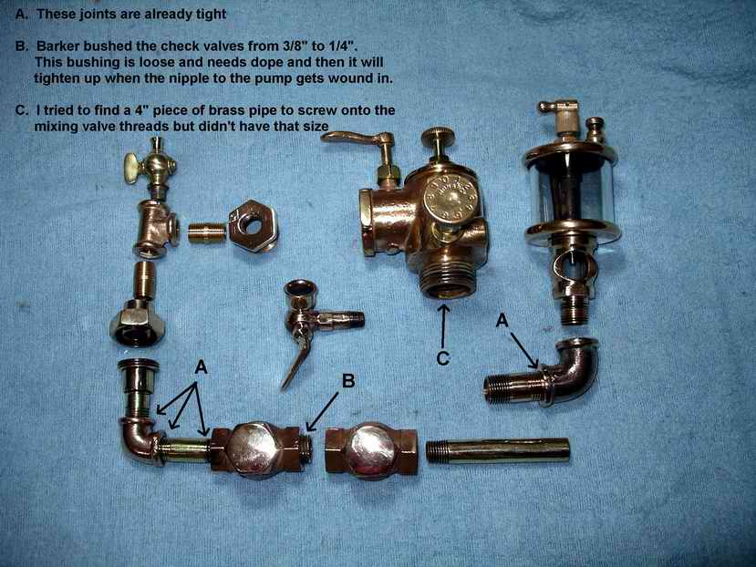 |
    
searcher
Senior Member
Username: searcher
Post Number: 356
Registered: 10-2004
| | Posted on Tuesday, October 13, 2009 - 05:19 pm: | 


|
George,
The box of Barker bits and pieces left the Post Office today by priority mail in a flat rate box. They could show up at your shop as soon as Saturday but more likely it will be early next week. I can take no credit for the great wooden box they are packed in. Dick Day built that. |
    
searcher
Senior Member
Username: searcher
Post Number: 359
Registered: 10-2004
| | Posted on Saturday, October 24, 2009 - 10:49 am: | 


|
George,
Did that box of parts for the Barker arrive? They left here on October 13th. |
    
george_iv
Senior Member
Username: george_iv
Post Number: 81
Registered: 07-2003

| | Posted on Sunday, October 25, 2009 - 11:14 pm: | 


|
Hello Searcher,
Yes I go the box the other day. I've been busy puzzling through the connecting rod. I actually posted some new pictures on the website of the rod I made but I don't think the rod will work. It seems I'll make a new rod this week. If I can get it done this week, I think I can have the Barker running by the end of next week. I'll take movies to share when that happens.
George |
    
george_iv
Senior Member
Username: george_iv
Post Number: 84
Registered: 07-2003

| | Posted on Monday, December 28, 2009 - 11:27 am: | 


|
Hello All,
Happy New Year and I hope the Holidays were good to you.
I am happy to report the Barker was removed from the STATIC DISPLAY designation this morning. At 10:30 after some carb issues, the Barker popped to a new life. She ran about 5 minutes and is easily hand cranked against her own compression. We ended up using a dribbler instead of the Monarch mixer but she does run well.
Tomorrow we will tear her down and do the final finishing up stuff. I'll post movies tomorrow also; probably on the website.
Three years later, boy what a rush to hear her run!!!
George IVy |
    
ernie
Senior Member
Username: ernie
Post Number: 1143
Registered: 01-2002

| | Posted on Monday, December 28, 2009 - 12:32 pm: | 


|
Neat!
And a happy New Year to you guys too
Ernie |
    
robert
Senior Member
Username: robert
Post Number: 316
Registered: 07-2003
| | Posted on Monday, December 28, 2009 - 12:54 pm: | 


|
Better christen that engine "Lazarus Barker"!
Anything still needed for it George? |
    
john_archibald
Senior Member
Username: john_archibald
Post Number: 129
Registered: 08-2006

| | Posted on Monday, December 28, 2009 - 01:01 pm: | 


|
Hematite might be a better name.
Archibald
Northfield, Minnesota |
    
george_iv
Senior Member
Username: george_iv
Post Number: 85
Registered: 07-2003

| | Posted on Monday, December 28, 2009 - 02:17 pm: | 


|
Maybe lodestone at this point; after all the time and energy.
George IVy |
    
paulgray
Senior Member
Username: paulgray
Post Number: 69
Registered: 05-2003
| | Posted on Monday, December 28, 2009 - 03:27 pm: | 


|
Congrats George to a successful end to a long and sometimes tedious journey! So glad to hear you got her running reliably- it sure did turn out nice. Happy new year ace! |
    
solarrog
Senior Member
Username: solarrog
Post Number: 393
Registered: 03-2002

| | Posted on Monday, December 28, 2009 - 10:55 pm: | 


|
you made me look it up.
Hematite, also spelled as hæmatite, is the mineral form of iron(III) oxide (Fe2O3), one of several iron oxides. Hematite crystallizes in the rhombohedral ...
I didn't know this was the learning channel |
    
john_archibald
Senior Member
Username: john_archibald
Post Number: 130
Registered: 08-2006

| | Posted on Tuesday, December 29, 2009 - 12:34 am: | 


|
Sunshine,
I'm a mining engineer. Know a few minerals.
Archibald
Northfield, Minnesota |
    
solarrog
Senior Member
Username: solarrog
Post Number: 394
Registered: 03-2002

| | Posted on Tuesday, December 29, 2009 - 12:57 am: | 


|
hey, My friends all say I must have rocks in my head for collecting all these engines, I guess Im a specalist |
    
richardday
Senior Member
Username: richardday
Post Number: 837
Registered: 11-2003

| | Posted on Tuesday, December 29, 2009 - 07:44 pm: | 


|
An incredble piece of work in every way. Congratulations George there are few if any who can top your results. |
    
george_iv
Senior Member
Username: george_iv
Post Number: 86
Registered: 07-2003

| | Posted on Wednesday, December 30, 2009 - 02:04 pm: | 


|
OK. I posted a movie on my website of it running. Although there's no sound, you can see her running well.
Now imagine a big grin... That's me!
George IVy
http://www.ghcoates.com/Barker.htm |
    
john_archibald
Senior Member
Username: john_archibald
Post Number: 131
Registered: 08-2006

| | Posted on Wednesday, December 30, 2009 - 03:34 pm: | 


|
I kept waiting for Charlie Chaplin to walk on. Played it several times, still no Chaplin.
Archibald
Northfield, Minnesota |
    
searcher
Senior Member
Username: searcher
Post Number: 399
Registered: 10-2004
| | Posted on Thursday, December 31, 2009 - 12:58 am: | 


|
That little Barker was in such a sorry state when I hauled it home that I could not have imagined that it would run again. Hard to believe I'm looking at the same engine. George, that is quite an accomplishment, congratulations. |
    
andrew
Moderator
Username: andrew
Post Number: 1034
Registered: 11-2001

| | Posted on Thursday, December 31, 2009 - 09:34 am: | 


|
Congratulations George!
Thanks also for doing such a great job of documenting the process.    |
    
rbprice
Senior Member
Username: rbprice
Post Number: 282
Registered: 11-2001

| | Posted on Thursday, December 31, 2009 - 05:24 pm: | 


|
FANTABULOUS George - you are THE Master Restorer. |
    
axtion_jim
Advanced Member
Username: axtion_jim
Post Number: 31
Registered: 01-2006
| | Posted on Friday, January 01, 2010 - 12:33 am: | 


|
George I think you should just stand back and say to yourself, That was a hoot and give your self a good pat on the back. Well done,I learened something from you. Thanks Jim S |
    
solarrog
Senior Member
Username: solarrog
Post Number: 395
Registered: 03-2002

| | Posted on Friday, January 01, 2010 - 12:44 am: | 


|
What is that insulation material use to stablize the tempature, while welding. I have only brazed blocks and hope to learn something here
Roger |
    
johnny
Senior Member
Username: johnny
Post Number: 201
Registered: 03-2006

| | Posted on Saturday, January 02, 2010 - 10:26 pm: | 


|
I have said this a few times before on this website/forum and I am going to say it again. I really feel very fortunate to be able to communicate and learn from such professional and knowledgeable people that I have met on this website. I thank all you so much. I always look forward to coming on this site almost daily if I can because there is always something that is interesting. Also would like to thank Andrew for taking care of this wonderful site.
Great! job on the Barker engine guy's not to many people would have the ball's to take that job on.
Andrew, I have never seen it mentioned but do you collect any kind of yearly fee's or donations for keeping the site up? I sure would not mind contributing to help the cause.
Happy New Year! everyone. |
    
Fordson Man
Visitor
| | Posted on Monday, July 19, 2010 - 01:29 am: | 


|
Great Work on the Barker!
Would you happen to know or have any idea what the original color was of it? |
    
george_iv
Senior Member
Username: george_iv
Post Number: 89
Registered: 07-2003

| | Posted on Monday, July 19, 2010 - 09:55 am: | 


|
I'm not sure. I remember seeing pictures of one somewhere that was blood red. There was no color other that rust on the one I messed with. There's a picture of a green one in this thread.
George IVy |
    
searcher
Senior Member
Username: searcher
Post Number: 446
Registered: 10-2004
| | Posted on Monday, July 19, 2010 - 12:07 pm: | 


|
This is the best I can do. Somebody on this site may have access to an earlier catalog that refers to color and finish.
 |
    
searcher
Senior Member
Username: searcher
Post Number: 447
Registered: 10-2004
| | Posted on Monday, July 19, 2010 - 09:55 pm: | 


|
I should add that when Barker or other marine engine companies of the period painted the engines 'dark green', it seems to have been quite dark. Darker than the older John Deere green and much darker than the newer green. One thing I have noted is that paint that has been covered by caked on dirt, grease, and oil for a long, long, time is not necessarily a reliable indicator of the shade of the original color. A reaction between some dark green paint and the caked on layer can produce greens that are much lighter than the original and even greens that are distinctly on the blue side. On the other hand, some dark green paint, when totally exposed for a century, becomes near black. Sure wish they had published color chips in those days like those found in most current automobile sales brochures. |
    
john_archibald
Senior Member
Username: john_archibald
Post Number: 146
Registered: 08-2006

| | Posted on Monday, July 19, 2010 - 10:33 pm: | 


|
I have found that a nice green color is that used on Model A Ford engines. It is still available today from any of several Model A Ford restoration company catalogs. You can get it in a can suitable for brush application or in regular spray cans.
I'm doing an Atlantic, 4 Hp, this color. Looks great.
Archibald
Northfield, Minnesota |
    
searcher
Senior Member
Username: searcher
Post Number: 448
Registered: 10-2004
| | Posted on Monday, July 19, 2010 - 11:57 pm: | 


|
Thanks for mentioning that Ford green - I will try it. The Dark Hunter green is the closest I've found so far but it doesn't have as much pizzaz as I would like. |
    
richardday
Senior Member
Username: richardday
Post Number: 884
Registered: 11-2003

| | Posted on Tuesday, July 20, 2010 - 07:35 pm: | 


|
Some time back I mentioned that the Rowayton, CT. marine museum had a Barber in very good condition when I saw it back about 1970. As I remember it it was dark green. Perhaps someone who lives near there could take some green color chips and see if they can come up with a match. |
    
richardday
Senior Member
Username: richardday
Post Number: 885
Registered: 11-2003

| | Posted on Tuesday, July 20, 2010 - 07:42 pm: | 


|
OOP! should have said Barker. |
    
speleausmining
Advanced Member
Username: speleausmining
Post Number: 39
Registered: 10-2010

| | Posted on Wednesday, April 18, 2012 - 01:58 pm: | 


|
The other green Ford used (on the eary Model T) thats good for restorations was Brewster Green which is still available from Ford restoration places. It would probably be too dark for the Barker as it is a vary dark green to almost black. Same deal you can get it in spray cans,brushable, or ready to use in your paint spray gun. The other colour that surprizingly matches alot of old green paint is Glossy Olive Drab. I do not know where you can get it in the States but here in Canada Cloverdale Paints has the colour code for Gov. Of Canada Olive Drab you just need to specify you want it glossy. This engine is going to look so sharp once its all painted up. but you got to show it with the before pictures. |
    
searcher
Senior Member
Username: searcher
Post Number: 525
Registered: 10-2004
| | Posted on Thursday, April 19, 2012 - 09:36 am: | 


|
I painted the Barker a semi-gloss black. However, every minor imperfection shows so I want to redo it. I am winding my business down and retiring shortly. I will then have time to finish a lot of projects that have been lagging including redoing the Barker paint. I may try the Ford green on the new paint job.
I will make a video for uTube featuring the Barker before and after restoration (making and posting videos on uTube is another thing I need to learn how to do in retirement). I walk by that Barker several times a day here in my office and I never fail to marvel at what George Coates and company accomplished. |
    
jim_parrott
Senior Member
Username: jim_parrott
Post Number: 66
Registered: 06-2009
| | Posted on Friday, March 28, 2014 - 07:53 am: | 


|
Searcher,
I often share this thread with friends and co worker to show off the talent of the guys on this site.
Are there any more recent pictures/videos of the Barker since the last post?
Jim |
    
searcher
Senior Member
Username: searcher
Post Number: 608
Registered: 10-2004
| | Posted on Friday, March 28, 2014 - 08:18 am: | 


|
I built a base for the Barker and mounted a Roper Safety Propeller with it. The outfit looks pretty good. However, the Barker shakes like most two cycles and the base tends to exaggerate the movement. In short order, the nuts on every bolt start backing off. I want to try some springs to dampen the movement. Once I work the bugs out, I will post a video of the Barker running with the Roper. I have taken the Barker to a couple of shows. It is hard to believe how easy it starts. I have a photo of the Barker that I took prior to the Coates magic and blew that photo up to near poster size. People find it hard to believe the before and after. Tonight, I will post a still image of the outfit. |
    
johnny
Senior Member
Username: johnny
Post Number: 459
Registered: 03-2006

| | Posted on Friday, March 28, 2014 - 09:19 am: | 


|
More photos of the Barker finished restoration and a YouTube video of it running would really add to a great ending of such a great accomplishment. |
    
searcher
Senior Member
Username: searcher
Post Number: 609
Registered: 10-2004
| | Posted on Monday, March 31, 2014 - 12:17 pm: | 


|
Here are a couple of poor photos but you can get an idea where I'm trying to go with the Barker. I would take some better photos but the Barker has been moved to one side while I finish painting that half of the floor.
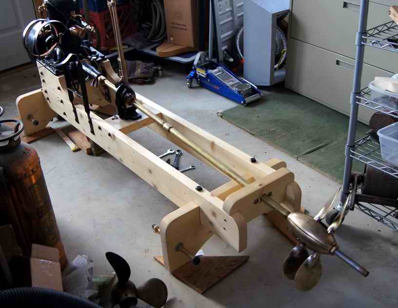
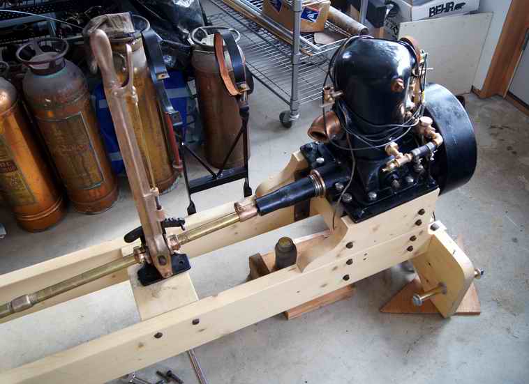 |
    
rbprice
Senior Member
Username: rbprice
Post Number: 457
Registered: 11-2001

| | Posted on Monday, March 31, 2014 - 01:08 pm: | 


|
That is a great arrangement Hugh, particularly the adjustable pitch propeller. |
    
johnny
Senior Member
Username: johnny
Post Number: 460
Registered: 03-2006

| | Posted on Monday, March 31, 2014 - 01:49 pm: | 


|
Wow! That is really going to be a nice running display. Great Job! The old engine deserves nothing less after all the work that has been put into it. |
    
searcher
Senior Member
Username: searcher
Post Number: 610
Registered: 10-2004
| | Posted on Monday, March 31, 2014 - 08:49 pm: | 


|
I wanted to be able to dismount the Barker easily so I put it onto skids designed to also mate up to a bracket attached to the base. I used a CAD program to draw the whole thing out including the mounting of the Roper Safety Propeller. Doing that allows one to see flaws in the concept, things that don't fit, how the angles come together for cutting, where the bolts go without interference, etc. It is a terrific adjunct to 'measure twice and cut once'.
I took the outfit to a show last fall and it all worked very nicely except for two things. I had a stuffing box to run the shaft through but I didn't have time to bore it 1/16" larger. Without that support, the prop tends to create some vibration.
The second problem is that the engine sits high and that tends to magnify the engine's jerks and jumps. After a few minutes running time, nearly every nut starts to back off. I can easily brace all the joints, use cotter pins, etc., but I really need to find a way to dampen the whole arrangment. I am going to try coil springs under the feet of the base to see if that helps. Any suggestions would be most welcome.
Bob and Johnny, thanks for the comments. |
    
jim_parrott
Senior Member
Username: jim_parrott
Post Number: 67
Registered: 06-2009
| | Posted on Tuesday, April 01, 2014 - 07:47 am: | 


|
That is a great looking display. It is good to see the Barker finished and painted.
I would suggest that you make the front of the base wider and running at minimum RPM's to help tame the beast. Try running with the prop shaft disconnected, if it is better reindex the prop and or blades if possible. |
    
johnny
Senior Member
Username: johnny
Post Number: 461
Registered: 03-2006

| | Posted on Tuesday, April 01, 2014 - 08:08 am: | 


|
The center of rotation is high off the ground from bottom where it sets. More weight closer to the ground to help hold it down would be good. Could pour four heavy concrete blocks with steel plates coming out of each block with mounting holes for each corner. Would be a lot of work to setup at shows.
That engine looks like a good candidate for it's own permanent trailer. If your going to put it on a trailer might as well get a boat also. |


