| Author |
Message |
    
mbashaw
New member
Username: mbashaw
Post Number: 1
Registered: 11-2010
| | Posted on Friday, July 22, 2011 - 07:38 pm: | 


|
I am almost ready to install the Dispro engine back into the boat and am not sure how to wire it up. This is what I think:
Wire from the plug to coil,
coil to the timer,
coil to kinfe switch to battery,
battery to other end of timer.
How did I do?
...and what size is each of these wires?
Thanks for the help! |
miro
Senior Member
Username: miro
Post Number: 577
Registered: 11-2001

| | Posted on Monday, July 25, 2011 - 08:39 am: |
|
There are 2 circuits.
A low voltage circuit which is the primary and that is the connection from the battery to the timer to the low voltage terminals of the coil and then back to the battery. Polarity doesn't matter.
The high voltage has 2 connections: The spark plug and the common point on the low voltage .
The common point of the low voltage is usually grounded to the engine.
The current in the primary is about 1-2 Amps, so a 16 guage wire ( preferably stranded) is OK - even 18 guage would work OK.
The high voltage is the usual spark plug wire ( not the carbon cored stuff)
miro |
mbashaw
New member
Username: mbashaw
Post Number: 3
Registered: 11-2010
| | Posted on Saturday, July 30, 2011 - 08:17 pm: |
|
What type of battery is appropriate? I seem to remember one of the guys telling us to use a 6 volt gel cell motorcycle battery. Would that be correct? |
johnny
Senior Member
Username: johnny
Post Number: 407
Registered: 03-2006

| | Posted on Saturday, July 30, 2011 - 09:36 pm: |
|
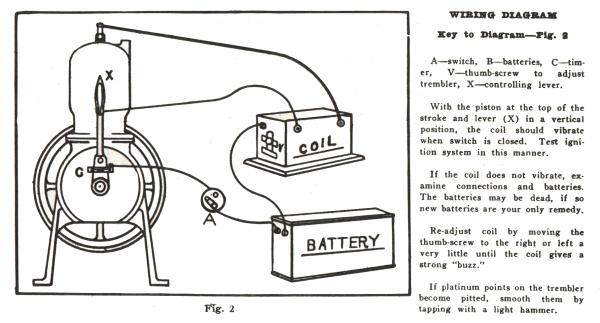
Maybe this will help.
 |
johnny
Senior Member
Username: johnny
Post Number: 408
Registered: 03-2006
| | Posted on Saturday, July 30, 2011 - 09:47 pm: |
|
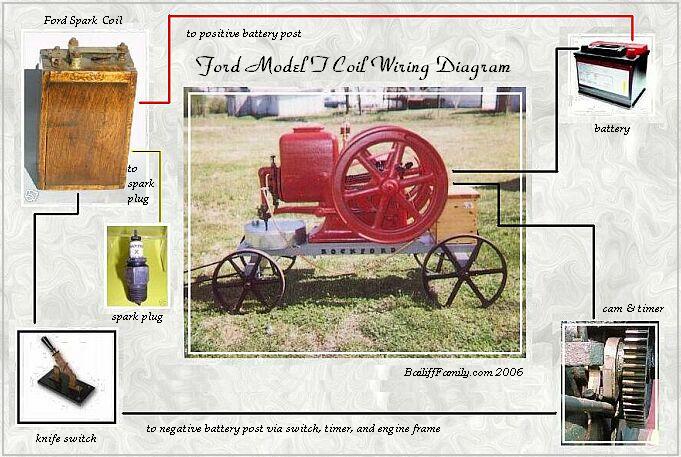
Here is a diagram using a model T coil. It's showing a stationary farm engine but it would still be the same for a spark plug style marine engine. Just put your timer lever or spark controller in place of there cam & timer they show in the pic.
 |
johnny
Senior Member
Username: johnny
Post Number: 409
Registered: 03-2006
| | Posted on Saturday, July 30, 2011 - 09:59 pm: |
|
I like to use 12 volt gel cell batteries. However I run engines mostly at shows. Some of the gentleman that have boats could probably give you better advice to what they like. If you use 6 or 12 volt just make sure you do not let your buzz coil buzz for longer then two or three seconds. The coils can get hot and burn out. They are designed to give a quick spark to the plug, just long enough to ignite the fuel. |
ernie
Senior Member
Username: ernie
Post Number: 1385
Registered: 01-2002

| | Posted on Sunday, July 31, 2011 - 08:22 am: |
|
I use 12 vots. Model "T" Fords ran on the mag which was 16 volts AC. I am using the same coil I have used for the last 20 plus years and it is always on 12 volts.
The battey box for my boat has 2 12 volt batteries in it with knife switches to select either or both. |
johnny
Senior Member
Username: johnny
Post Number: 410
Registered: 03-2006
| | Posted on Sunday, July 31, 2011 - 09:14 am: |
|
Ernie, I think I remember seeing a photo of your battery box and coil setup on the forum. Didn't you use two 12 volt gel cells? Do you recall what the amps were? The 12 volt gel cell batteries I'm using are only about 7 or 8 amps. I think my Batteries are about half the size of what you use. Mine may not last long enough for a good boat ride. |
richardday
Senior Member
Username: richardday
Post Number: 970
Registered: 11-2003

| | Posted on Sunday, July 31, 2011 - 09:15 am: |
|
Wire one battery + to ground and the other - to ground and you will minimize point build up. |
ernie
Senior Member
Username: ernie
Post Number: 1386
Registered: 01-2002
| | Posted on Sunday, July 31, 2011 - 11:06 am: |
|
You mean so you get a polarity change when you switch from one battery to the other?
Johnny I will have to fo look at the amps on the baterys
More later |
jb_castagnos
Senior Member
Username: jb_castagnos
Post Number: 609
Registered: 07-2002

| | Posted on Sunday, July 31, 2011 - 11:32 am: |
|
Dick, on our boats if you wire one way it will give a shock when reversing, switching polarity stops it. |
johnny
Senior Member
Username: johnny
Post Number: 411
Registered: 03-2006
| | Posted on Monday, August 01, 2011 - 06:22 am: |
|
Richard, I would like to see a wiring diagram of how you do that. Do you have a diagram by chance that you could post? Making the contact points last a little longer is a good deal. No one likes to get stranded way out on the lake or river somewhere. |
johnny
Senior Member
Username: johnny
Post Number: 412
Registered: 03-2006
| | Posted on Monday, August 01, 2011 - 06:44 am: |
|
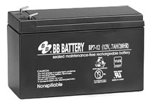
Here is the type of battery I use. I said gel cell in my previous post but they are actually a sealed lead acid battery. I think this is the same type of battery Ernie is using, his is larger and probably more amps. The battery pictured below is a 12 volt 7amp cost about $20 dollars or less. The more amps the higher the cost.
 |
johnny
Senior Member
Username: johnny
Post Number: 413
Registered: 03-2006
| | Posted on Monday, August 01, 2011 - 07:20 am: |
|
Richard, I'm not an electrical person but I have been thinking about what you said and it seems like to me if you had two 12 volt batteries connected in Parallel and did what you said it would be a direct short? I think you could do it if your batteries were connected in series however you would need two 6 volt batteries and you would then have the 12 volts using the jumper between the two batteries to go to ground. A positive lead from one battery to ground and a negative lead to ground from another battery. Is this what you are talking about? |
richardday
Senior Member
Username: richardday
Post Number: 972
Registered: 11-2003
| | Posted on Monday, August 01, 2011 - 07:40 am: |
|
The answer is the old timers had a simple switch center off, one side to the + battery and the other side to the - battery. |
mbashaw
Member
Username: mbashaw
Post Number: 6
Registered: 11-2010
| | Posted on Tuesday, July 17, 2012 - 05:05 pm: |
|
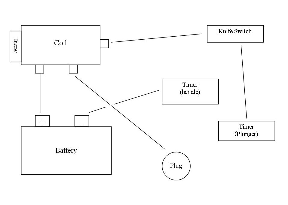
Here is what I have currently wired together.
Does anyone see issues?
Thanks
 |
johnny
Senior Member
Username: johnny
Post Number: 444
Registered: 03-2006
| | Posted on Tuesday, July 17, 2012 - 06:16 pm: |
|
If the "timer plunger" is your contact points & timer then I believe it will work. |
ernie
Senior Member
Username: ernie
Post Number: 1535
Registered: 01-2002
| | Posted on Wednesday, July 18, 2012 - 07:07 am: |
|
Nice Drawing
The knife switch should go in the lead from battery positive to the coil.
The reason is that if the wire from the coil to the knife switch shorts to ground you will not be able to shut the coil off.
Hope this helps
Ernie |
bcm
Advanced Member
Username: bcm
Post Number: 38
Registered: 11-2009
| | Posted on Wednesday, July 18, 2012 - 10:42 am: |
|
Here are some suggestions:
Circuit attached
1 Knife switch also functions as a battery disconnect switch, that�s the advantage of using a knife switch
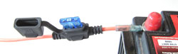
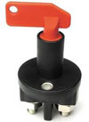
2 If you use a push-pull switch, install a battery disconnect unit, see image
3 Install an in-line fuse next to battery, see image, if vibrator point malfunction fuse will blow rather than overheating and damaging coil.
4 Use crimp style ring connectors, use stranded wire, colour coded.
5 Solid conductor spark plug wire is better, but may cause RF interference.
6 If you use small battery as illustrated in another post, carry a spare fully charged.
7 Use 12 volts, spark is much better than when using 6 volts
8 Learn to adjust vibrator for least current needed for strong spark. This will extend battery life
9 Gell cell is ok, AGM battery is better. Learn about battery voltage corresponding to 100%, 50% charge. Charge battery when voltage is at 50% charge. Be sure charger rate matches battery.
 |