| Author |
Message |
    
bill_friday
New member
Username: bill_friday
Post Number: 2
Registered: 08-2016
| | Posted on Friday, August 26, 2016 - 10:42 pm: | 


|
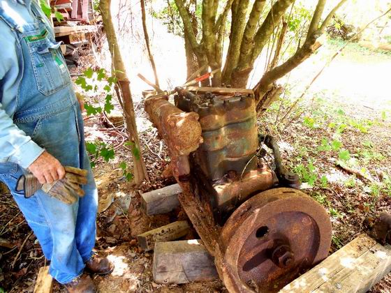
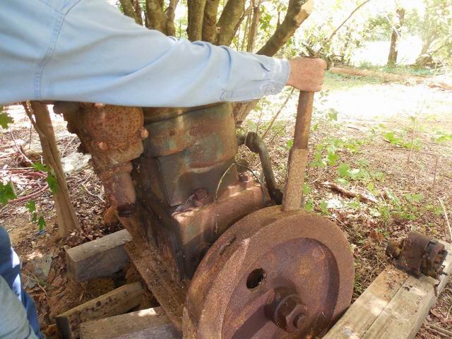
We are working to restore an old Regal 2-cylinder marine engine and have some technical questions. The pistons are 6.75" dia and the stroke is 7.25". There are two spark plugs each side, and the magneto fires in even rotation order. The magneto is driven 1:1 with the crank. The cam gear was broken and so we lost the timing. Now the gear is repaired but we can't understand how to re-set the timing. The crank gear is 4", the cam gear is 8", but there is a 6" intermediate gear, which carries the timing mark (we think, as this thing is very rusty inside). We also are having trouble freeing the clutch assembly and could use some guidance, particularly a repair manual. Any help for us?[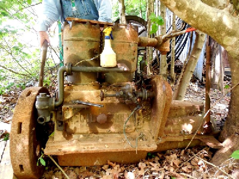 |
ernie
Senior Member
Username: ernie
Post Number: 2310
Registered: 01-2002
| | Posted on Saturday, August 27, 2016 - 08:29 am: |
|
Bill,
You can set the cam timing so cylinder number 1 exhaust cam/valve is just closing and the intake cam/valve is just starting to open at TDC. Just center the valve motion between the above points. This will then be what is commonly known as "TDC exhaust".
The mag will need to fire at "TDC compression which will be 360 deg from the point where you set the cam timing for number 1 cylinder. Since you describe this as an even fire engine cylinder number 2 will automatically fall into time.
However since you describe this as an even fire engine the mag will fire at every TDC, just for the other cylinder. At number 1 TDC exhaust the mag will fire for number 2 TDC compression etc.
An even fire engine has both crank pins in line so both pistons go up and down together.
If it is odd fire like a John Deere tractor timing the mag has an additional step as you have to make sure the mag timing is the same as the valve timing due to the crank pins being opposite.
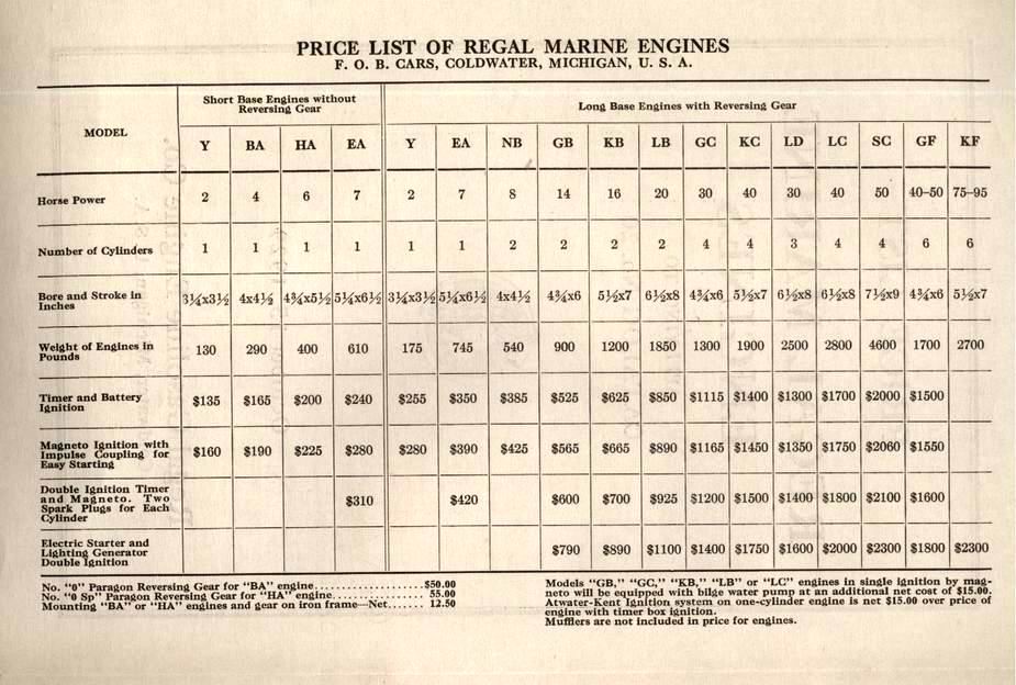
From what I can see the reverse gear looks "Paragon" style. There will be a drum and a band visable when removing the cover. Inside the drum will be a clutch and a planetary gear set. Let me know if this is what it looks like and I will try to find an exploded view picture of that style of reverse gear.
Can you post more pics? Or you can e-mail them to me and I will post them for you.
Hope this helps
Ernie
e-mail me for more info or assistance. |
bill_friday
New member
Username: bill_friday
Post Number: 3
Registered: 08-2016
| | Posted on Saturday, August 27, 2016 - 09:31 am: |
|
Ernie,
Thanks for the information. In an ordinary engine, several things would make this a simpler process, but ours has some odd features that cloud the logic.
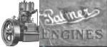
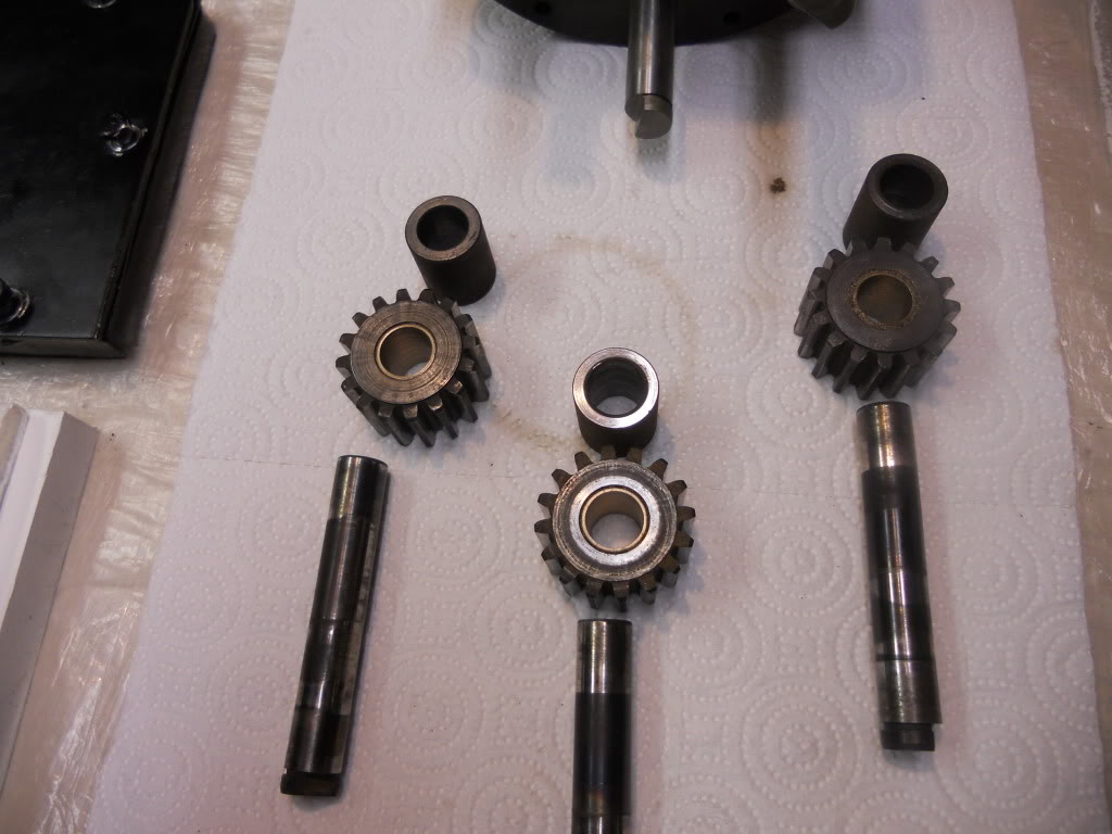
The 6" idler gear between the 4" crank gear and the 8" cam gear carries the timing mark, but it isn't a 1:1 rotation sequence. There are rotations where the timing marks are not aligned, and yet the engine is correctly timed - you just can't verify it. After several more rotations, the marks would align - we just have to keep spinning the engine to find the one where they are correctly aligned, and starting with the cam gear in hand we are a bit flying blind. Observing the cam lobes, we see that the left lobes for each cylinder are aligned, and the right lobes are rotated by most of a circle - does this mean that the intake and exhaust are swapped on the two cylinders? The pistons are exactly opposite - one reaches the top just as the other reaches the bottom, which is comforting.
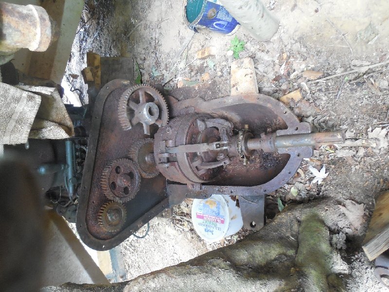
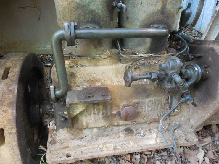
And then there is the magneto. Each piston has two spark plugs. The magneto shaft is geared to run the same speed as the crank (two larger idlers in between). I've attached a photo of this gear wall. The broken cam gear in the picture is now adequately repaired and functional. The magneto itself fires each of its four outputs in even sequence. I've not had the magneto alongside the engine to see if it has any internal gearing to speed it up or slow it down. Maybe the fellow who has it in his shop can check that. So why two plugs, and how do they fire relative to the TDC's for the two cylinders.
And finally, once we get the engine ready to run, there is this big chunk on the output shaft. It acts like a clutch, which would be a necessary feature for a boat engine, but an old ad we found on this Old Marine Engine website calls it a reverser, also a useful feature for a boat. And it obviously has a brake on the outboard end, not obviously a necessary feature, but there it is.
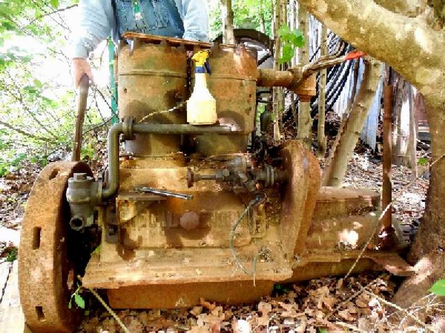
We are so close, and it is such a beautiful old beast that we cannot just walk away. It belongs to a friend who has graciously allowed us to have the pleasure of restoration. I watched a video online of a boat engine of this size running, and the sound was magical. I want to hear it up close.
Thanks again
Bill Friday, Burton Marsh, and Buddy Randolph
 |
bill_friday
Member
Username: bill_friday
Post Number: 4
Registered: 08-2016
| | Posted on Saturday, August 27, 2016 - 09:51 am: |
|
Ernie,
Apologies that I'd not read all of your message. I got an abbreviated version sent directly to me from Old Marine Engines, so I missed the extra and very useful information you had included until after I'd sent my previous reply.
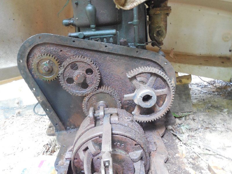
A few more photos are attached. They are low resolution to fit in the small server space allowed. I notice that there is an impulse clutch on the magneto, which is a necessary feature for hand cranking. It is even firing. |
ernie
Senior Member
Username: ernie
Post Number: 2311
Registered: 01-2002
| | Posted on Saturday, August 27, 2016 - 05:06 pm: |
|
1 the odd number of revolutions and marks on the idler gear are so the load on the cam gear teeth are spread around and don't wear the same few teeth every other revolution. That is why the timing marks only line up every once in a while.
2 mag timing. Time the mag to number 1 TDC compression. Which ever terminal the rotor in the mag points to will have a wire to 1 of the number 1 cylinder plugs. Then while turning the the engine over see which mag terminal the rotor is pointing to on the next TDC compression. That terminal will go to one plug on the number 2 cylinder. Ground the other 2 mag terminals as they won't be used but can't be left with no place for the spark to go or mag damage can occur.
You will only be using 1 plug on each cylinder.
3 you say 1 piston is up and the other is down which makes this engine odd fire because it is basically 1/2 of a 4 cylinder. It will fire 1-2 then have 270 degrees of nothing like a John Deere 2 cylinder.
Send me an e-mail and I will give you my phone if you want to discuss this in depth.
Good luck
Ernie |
ernie
Senior Member
Username: ernie
Post Number: 2312
Registered: 01-2002
| | Posted on Saturday, August 27, 2016 - 05:21 pm: |
|
The chunk on the rear end is a reverse gear having forward at 1 to 1, neutral and reverse at some ratio other than 1 to 1.
It works by locking an internal clutch for forward which is done by the fingers on the aft end.
Neutral is to release that clutch and also have the band/brake released
Reverse is the band/brake on the outside which will hold the drum causing the internal planetary gears to turn the output shaft in reverse.
There are 2 pics below of this style of reverse gear.
 |
bill_friday
Member
Username: bill_friday
Post Number: 5
Registered: 08-2016
| | Posted on Saturday, August 27, 2016 - 06:10 pm: |
|
Ernie,
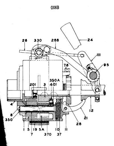
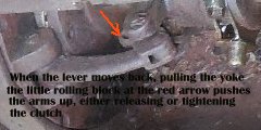
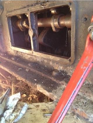
These two posts are most illuminating. I'm very familiar with the John Deere firing sequence. We should be able to whip it into shape now, except for freeing up the reverser. We can crank the engine and just let it spin in whatever mode it is stuck. We had found the diagram you sent above, but it is for a later model, is fuzzy, and is hard to interpret without knowing already what we have. I do see the planetary gears and the brake. In the attached closeup, if you look closely at the links for the clutch, when the lever is pulled back it spreads and locks the three arms. It isn't obvious if this tightens or releases the clutch. The bar that actuates the brake is also different from the diagram, and very worn - not clear which way clamps the brake band. From the displacement and appearance, do you know what model and HP this engine is? Is there any way for me to contact you directly without putting my email or phone in this message?
 |
ernie
Senior Member
Username: ernie
Post Number: 2316
Registered: 01-2002
| | Posted on Saturday, August 27, 2016 - 08:39 pm: |
|
Bill,
Just click my name to the left and my e-mail is there.
Neat engine and neat project.
I wish you were closer.
Ernie |
robert
Senior Member
Username: robert
Post Number: 735
Registered: 07-2003
| | Posted on Sunday, August 28, 2016 - 05:12 pm: |
|
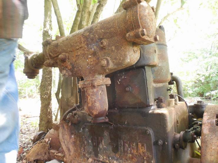
Nice to see an engine with all the brasswork still in place. Is it possible this engine had dual ignition in the form of the magneto and a battery, coil and timer? Quite common up here to see that.
Interesting that the hub is split on the camshaft gear; looks like the maker forsaw this problem! Two keys as well?
I wonder if running a set screw or a long shank bolt in from each side of the slot until their ends pushed against each other, would actually spread the hub just that little bit more than just undoing the set screw would? Or do the screws run through a relief cut in the shaft? If that were the case, I guess one would just spread the hub, insert sufficient shims to hold the "spread" and then remove the set screws/bolts?
Or is this all just a figment of my imagination!?
The "Johnson bar" holes in the flywheel look downright dangerous: no relief or 'ramp' at the end of the holes to encourage the bar to fall out if the engine starts? |
bill_friday
Member
Username: bill_friday
Post Number: 6
Registered: 08-2016
| | Posted on Sunday, August 28, 2016 - 10:35 pm: |
|
Robert,
The starter bar is rounded on one edge such that when the flywheel spins past that point, the bar is safely forced out of the pocket. There is no evidence that the engine used anything other than the magneto for spark generation. The hole through the cam gear isn't threaded, and it slides the bolt through a cross groove in the shaft - triple safety.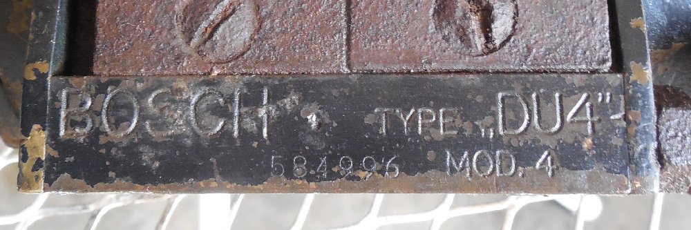  |
ned_l
Advanced Member
Username: ned_l
Post Number: 43
Registered: 08-2012
| | Posted on Monday, August 29, 2016 - 12:53 pm: |
|
If you haven't caught onto it yet, the "brake band" is not a brake band as you may think. When the shift lever is pulled back, that band does close and grab the drum, but that is when the 'planetary gears' inside the drum come into use and actually cause the output shaft (propeller shaft) to turn in the opposite direction (reverse). that gearbox is 'forward-neutral-reverse', there is no brake.
That same design was used by Chris Craft well into the 1960's.
Definitely an interesting engine.
|
bill_friday
Member
Username: bill_friday
Post Number: 7
Registered: 08-2016
| | Posted on Monday, August 29, 2016 - 01:30 pm: |
|
Thanks for the clarification. Ernie had explained it that way so I had a good idea about it. Boats don't really need a brake as such, rather using the prop to stop the motion.
Any suggestions for how to get this lump of rust opened, cleaned, greased, and operational? |
ned_l
Advanced Member
Username: ned_l
Post Number: 45
Registered: 08-2012
| | Posted on Monday, August 29, 2016 - 03:05 pm: |
|
I have a number of pictures of the inside of a Chris Craft reverse gear that I can post so you can see what is inside.
first I have to remember how to post pictures here. .........ok, got that figured out, now I have to figure out how to reduce the file size. of each picture |
bill_friday
Member
Username: bill_friday
Post Number: 8
Registered: 08-2016
| | Posted on Monday, August 29, 2016 - 03:59 pm: |
|
For file sizing I use an ancient picture manager that allows direct scaling, plus a lot of other processing. If I ever lose it I'm sunk.
Or you can pull my email by clicking my name on the left and then send me the full size photo(s).
You can see the chunk (likely a Paragon type) in some of the above photos, plus a schematic of one that is similar but apparently newer.
I think they all work on the same principal - lever forward is forward, middle is neutral, lever back is reverse, or the other way around. |
johnoxley
Senior Member
Username: johnoxley
Post Number: 158
Registered: 04-2010
| | Posted on Monday, August 29, 2016 - 04:29 pm: |
|
Hi - Try tub of cheap vinegar and soak the gearbox for days/week, etc. Often effective. Steel and iron parts come out black but derusted. Molasses also effective. Lots of www sites on electrolytic cleaning as well. Usually 3 by spur gear clusters that reverse (and reduce speed) output shaft. Union did make a bevel gear design that gave 1:1 reverse though. Gearbox will function for display even if loose and noisy. Pack with grease. Full rebuild needed if gearbox going into boat. |
ned_l
Advanced Member
Username: ned_l
Post Number: 46
Registered: 08-2012
| | Posted on Monday, August 29, 2016 - 05:38 pm: |
|
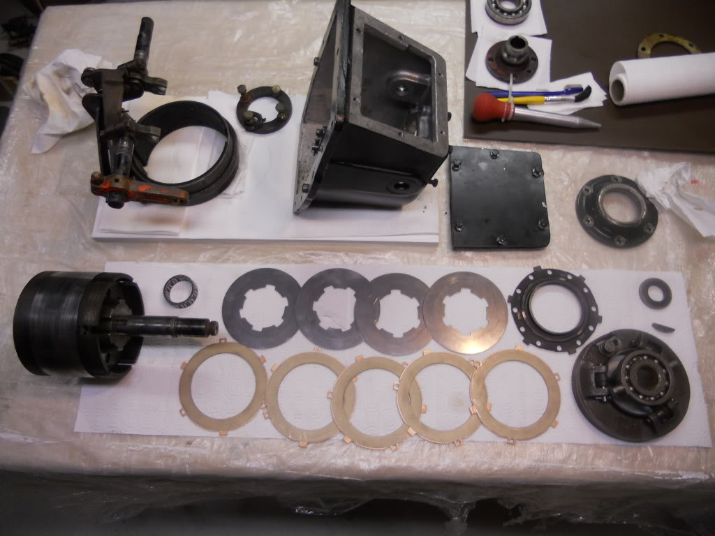
OK, making headway here. I have others that I will work on getting up tomorrow (maybe, it will be a busy day).
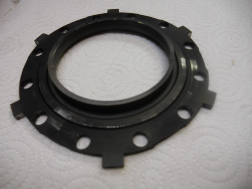
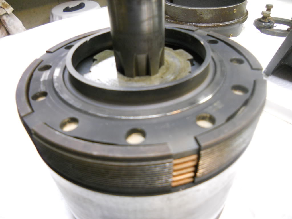
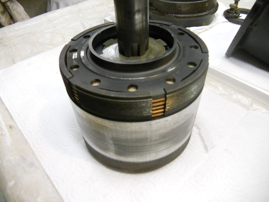
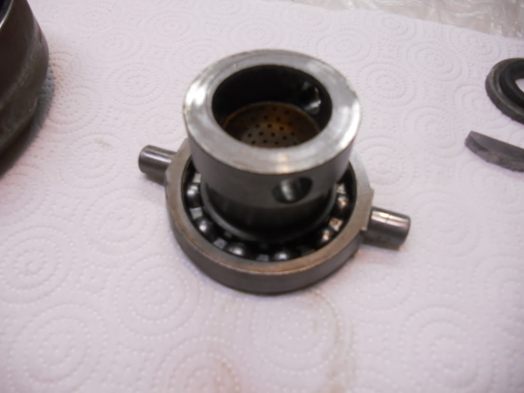
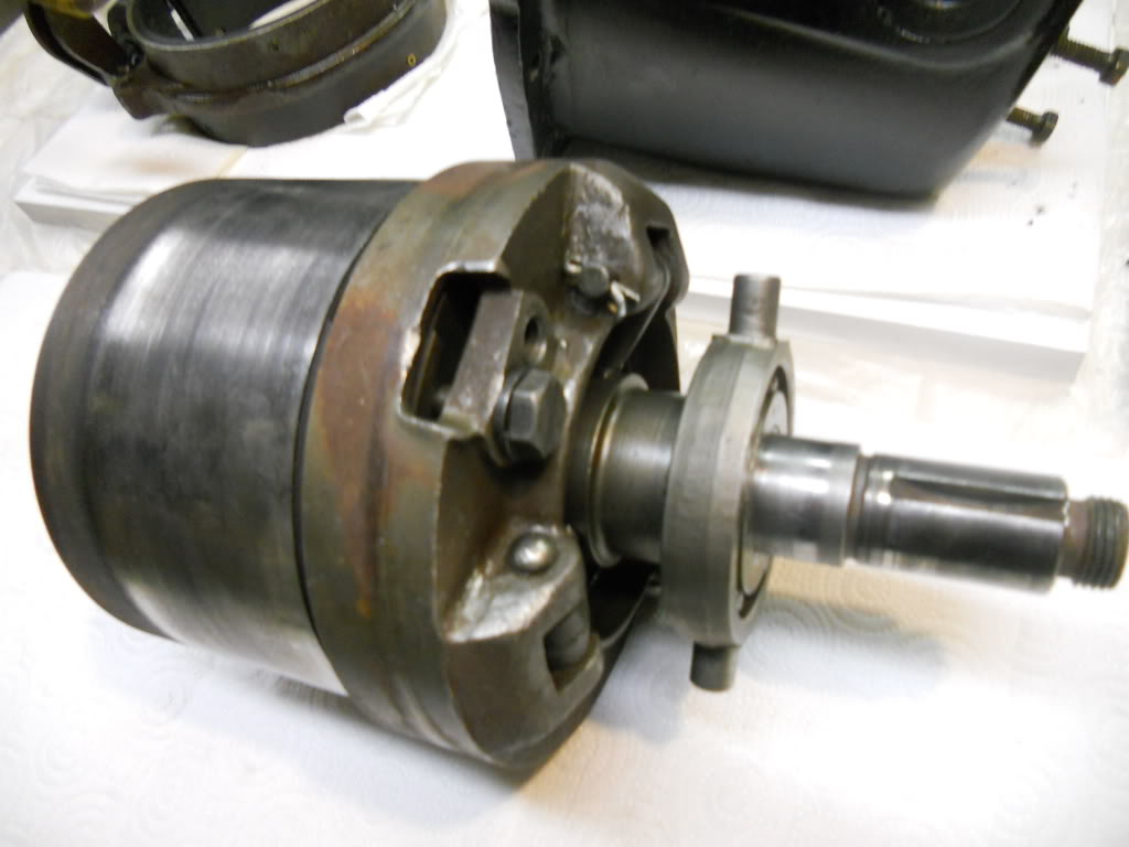
When you take the gearbox apart, the "drum" will unscrew to reveal the clutch plates. The three 'fingers' press on the first 'cover plate' (with all the holes) and squeeze the clutch plates together. If you look at the stackup of clutch plates you can see they alternate - splined on the inside - splined on the outside, etc. The splines (or tabs) lock the plate to either the central shaft or the outer drum. When released, the plates slip on each other so the central shaft can turn without the outer drum turning. When you put it in gear (forward) the three fingers push that end plate in and press all the clutch plates together, which makes the outer drum turn when the center shaft turns. |
ned_l
Advanced Member
Username: ned_l
Post Number: 47
Registered: 08-2012
| | Posted on Monday, August 29, 2016 - 05:58 pm: |
|
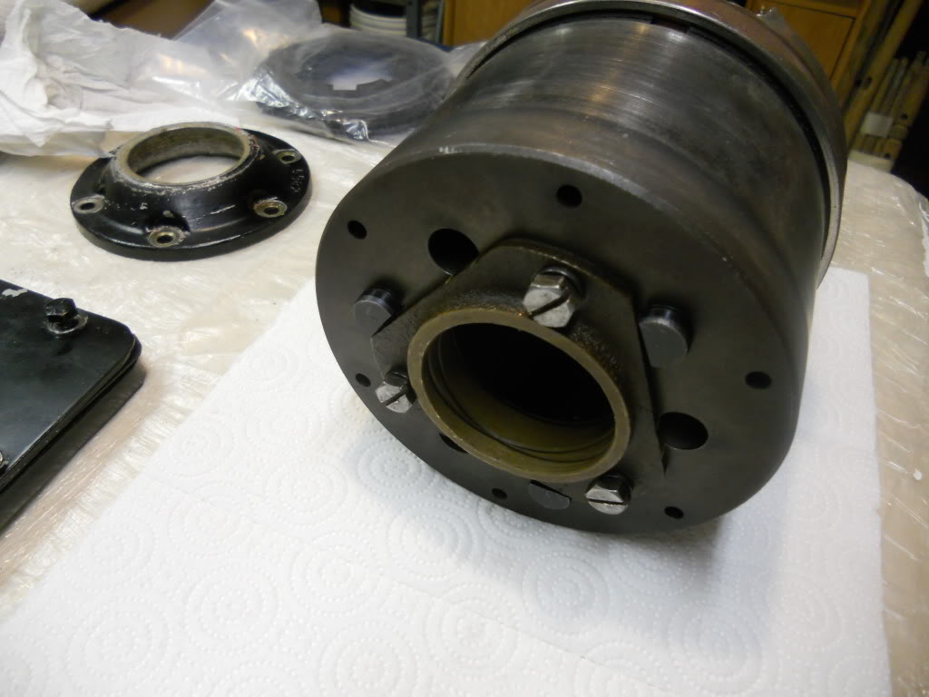
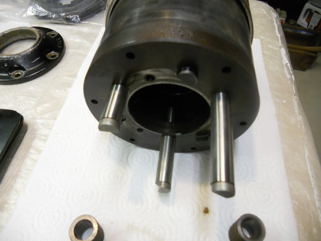
I'll resized the pictures and figured I'd get them up here now. Sorry, don't have time to explain, but it should give you something to look at and ask about.
 |
ned_l
Advanced Member
Username: ned_l
Post Number: 48
Registered: 08-2012
| | Posted on Monday, August 29, 2016 - 05:59 pm: |
|
 |
ned_l
Advanced Member
Username: ned_l
Post Number: 50
Registered: 08-2012
| | Posted on Monday, August 29, 2016 - 06:04 pm: |
|
 |
ned_l
Senior Member
Username: ned_l
Post Number: 51
Registered: 08-2012
| | Posted on Monday, August 29, 2016 - 06:05 pm: |
|
 |
bill_friday
Member
Username: bill_friday
Post Number: 9
Registered: 08-2016
| | Posted on Monday, August 29, 2016 - 11:34 pm: |
|
Thanks Ned.
With the text descriptions I can visualize how some of these parts work together. Our problem is the we don't know how many parts in ours have similar functions. And we don't know how to disassemble it, or even get it loose from the crankshaft. What manufacturer made the one in the photos? Our is probably a Palmer. For now we will concentrate on getting the engine ready to run and just let the chunk spin harmlessly on the tail shaft. You can see ours in a couple of the photos above, so if you see any clues as to how we can disassemble it, let us know.. Thanks again. Bill |
richarddurgee
Senior Member
Username: richarddurgee
Post Number: 3855
Registered: 11-2001
| | Posted on Tuesday, August 30, 2016 - 06:07 am: |
|
*
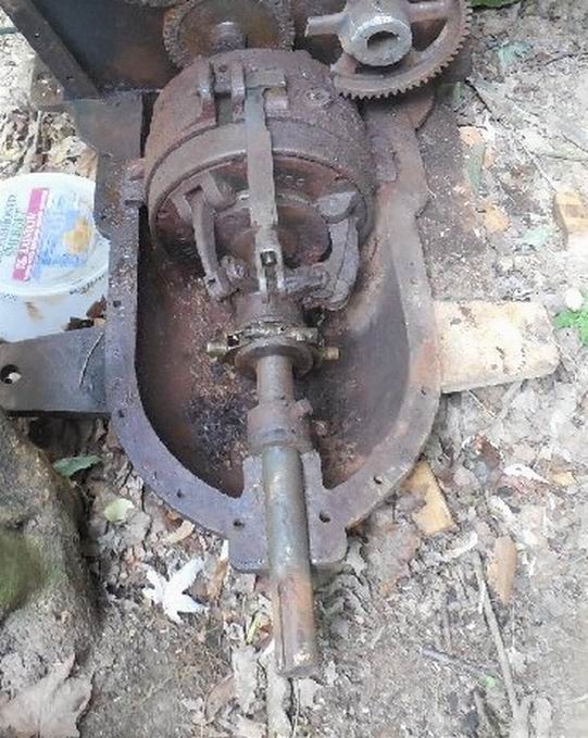
This photo shows a collar with a square
head set screw at the very aft of the output shaft
just inside of the case, there is what appears to be a thrust washer or a rusted together three piece thrust bearing between the collar and the case ? I would emery paper and oil the shaft ahead of the collar take the set screw out and slide the collar and bearing forward, that may allow the the transmission to slide back from the engine ? If the bearing is indeed a bearing and rusted together that should be dealt with before running, the shaft may still want to spin even in neutral it will damage the thrust face of the case ?
Very cool Old Marine Engine and a great project !
* |
bill_friday
Member
Username: bill_friday
Post Number: 10
Registered: 08-2016
| | Posted on Tuesday, August 30, 2016 - 06:45 am: |
|
That is a bearing at the near end of the shaft, made of two plates capturing a set of ball bearings. We loosened it and the balls fell out. After moving the bearing toward the chunk, we "encouraged" the chunk to move. All documentation so far says the chunk should separate, leaving half on the engine and the other removing the tail piece of the shaft. Too much rust, and there are probably some bolts connecting the halves that we have not found. We are off on another project this week while the Regal sits and ponders its fate. Thanks |
ned_l
Senior Member
Username: ned_l
Post Number: 52
Registered: 08-2012
| | Posted on Tuesday, August 30, 2016 - 01:00 pm: |
|
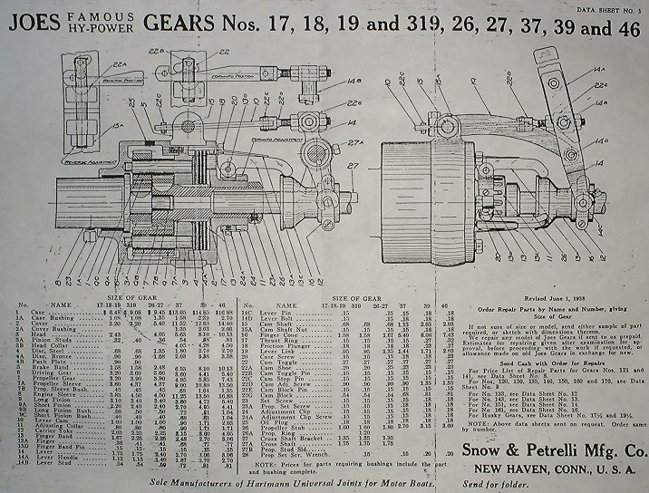
the diagram of the "Joe's Gear" above shows that the 'chunk' or drum has a coupling with a set screw that slides on the crankshaft of the engine.
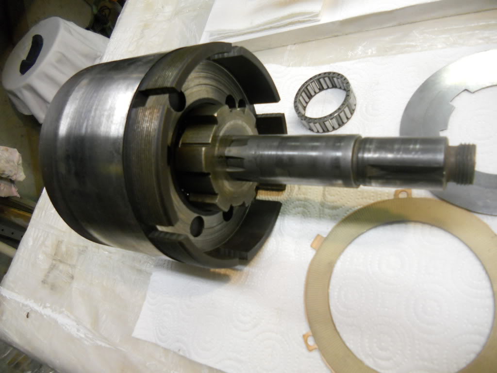
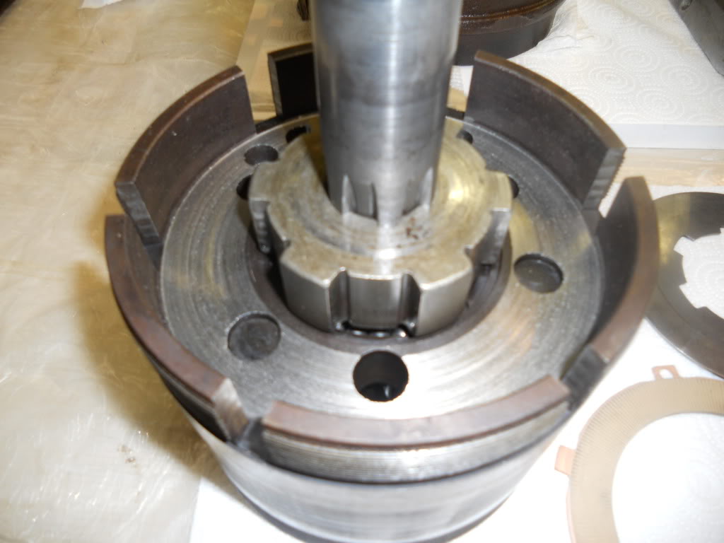
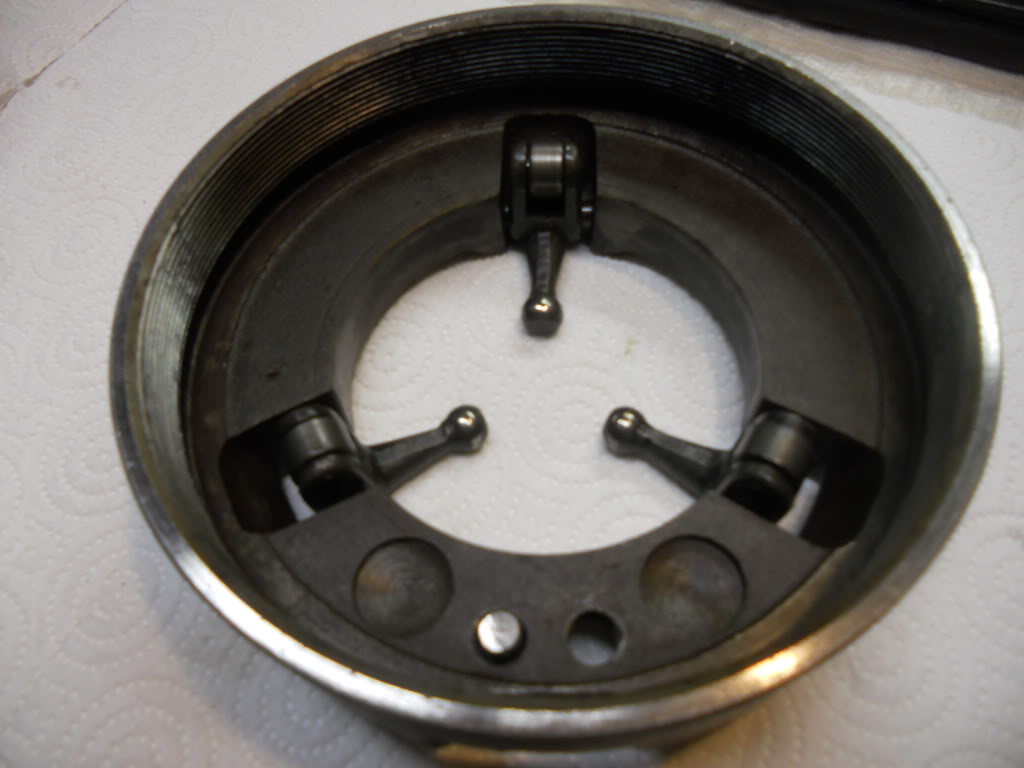
On the Paragon gear that I posted, there is a splined stub shaft that presses onto the crankshaft, then the drum slides over the stub shaft. On the Paragon gear the 'drum' does come apart. It unscrews where the outer diameter is stepped. I would suspect yours is similar, it may unscrew right at the aft end of the reverse gear band. Or (looking at the pictures) the face of the drum (where those three fingers are) may unscrew/come off of the drum some how.
You do need to first figure out how to get the guts out of the housing and off the engine. |
johnoxley
Senior Member
Username: johnoxley
Post Number: 159
Registered: 04-2010
| | Posted on Tuesday, August 30, 2016 - 06:00 pm: |
|
Chrysler design on M6 and M8 engines is similar but thread in internal in housing. Clutch discs similar and released by removing a small lock plate and unscrewing the entire rear plate and removing clutch pack. Then the reverse section could be removed.
This also is how the clutch pack was adjusted. |
bill_friday
Member
Username: bill_friday
Post Number: 11
Registered: 08-2016
| | Posted on Tuesday, August 30, 2016 - 11:03 pm: |
|
Lots of great advice, and it is all appreciated, but best we can tell, this engine spent some time in the hull of a sunken boat, and the corrosion has made the chunk into such a solid block of rust that it isn't a matter of unscrewing or unbolting, more like dynamiting. Ernie thinks it is a Palmer, so that company's designs will give us the best chance of getting something to turn loose. It isn't a big worry, because we can run the engine with the chunk frozen, and it will just spin like the clutch was set in forward - could be worst. Really though, thanks for all the inputs. It shows that this forum is well used. |
robert
Senior Member
Username: robert
Post Number: 739
Registered: 07-2003
| | Posted on Wednesday, August 31, 2016 - 10:58 am: |
|
Steam clean it or clean it off outside with oven cleaner, find the fill plug on the casing and remove it if you can, perhaps by careful use of an impact driver - the kind you hit with a hammer, not an air impact gun. Use some oxy-acet. heat on the plug if you have to but not to red heat as you may split the casing around it. Once you have the plug out you can drain any oil left in there. Fill it full of solvent if you have a solvent tank big enough to sit the gear in. You could put the solvent hose right in the filler plug hole and flush inside perhaps. After getting it as free of dirt and oil as you can you could glass bead the exterior. That may allow you to start the disassembly. If the parts are still too frozen, you'll have to use some careful heat, or soak it in vinegar (acetic acid to be precise) for a few weeks, followed by a pressure washing preferably a steam cleaning. The trouble is that dirt and oil prevent the vinegar from getting into the places it needs to go to dissolve the rust. You could also put it in an automotive "hot tank" for a week; in fact that would be the best preparation for blasting the exterior, if you can get the fill/drain plugs out first so the hot tank solution can get inside the gear. Once you get the rust and dirt off you'll see better how to get it apart. |
ned_l
Senior Member
Username: ned_l
Post Number: 54
Registered: 08-2012
| | Posted on Thursday, September 01, 2016 - 10:48 am: |
|
I'll just point out that there is no 'drain plug' in the gear case. It is not at all sealed. If it is oil lubricated, the outer housing is partially filled with oil (just like the engine crank case) and the whole gear case is partially immersed in, and spinning in oil. |
robert
Senior Member
Username: robert
Post Number: 740
Registered: 07-2003
| | Posted on Thursday, September 01, 2016 - 11:00 am: |
|
Fair enough Ned, but on the Joe's Gear brochure scan above, which I do believe I posted here about ten years ago, item 25 is indeed the "oil plug" and all of my gears have them IIRC. As you have a sealed cover over the gear I guess it's quite possible it was lubricated in a different way from those gears that were open. They were known for slinging oil around and some owners and builders did put sheet metal guards over them to catch the 'spray'. |
ned_l
Senior Member
Username: ned_l
Post Number: 55
Registered: 08-2012
| | Posted on Tuesday, September 06, 2016 - 08:48 am: |
|
Robert, interesting that some gear cases are 'sealed' and have drain plugs. Thank you for that information an pointing that out on the diagram.
-- The pictures I posted are of a Paragon gear off the back of a 1960's Chris Craft marine engine that years ago was 'repurposed' onto a SBC 350 in a retired race boat. |
bill_friday
Member
Username: bill_friday
Post Number: 12
Registered: 08-2016
| | Posted on Wednesday, September 07, 2016 - 09:06 am: |
|
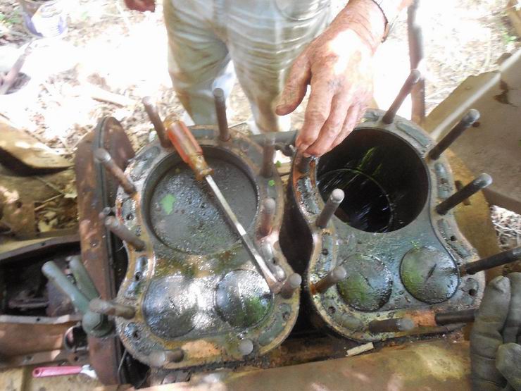
I�ve read through all of the correspondence concerning our old Regal engine and learned much - many thanks to all. This is my first experience with a marine engine, and they are very different beasts from steam and tractors. Most of the inputs concerned the reverser, which is still a solid block of rust, but I�ve developed a strong curiosity and hopefully enough understanding to coax it back to life. Meanwhile on the engine itself, we have gotten the cam gear welded back together in excellent form � beaten up but serviceable. Other info in pieces have given us understanding that the engine rotated counterclockwise (looking at the flywheel end), the firing pattern is the same as old John Deere Poppin� John�s, that is pop-pop-coast-coast. The cam shaft is exposed on the side so we could analyze the lobes and confirm rotation, confirm the outboard valves are exhaust, and confirm the firing pattern. The reverser interferes with getting the cam gear on and off of its shaft, so we shifted the cam shaft forward out of the front of the engine case (where an exterior eccentric actuates the water pump � this thing has rollers on the valve lifters!). TDC was located with a dial indicator, as was the exact position of the cam between exhaust valve close and intake valve open (no overlap in their opening). This allowed the determination of cam gear / crank gear mesh point (the timing marks were wiped out by corrosion). The cam gear was slid in place (it has two keys plus a cross bolt that catches a groove in the shaft and a lock nut on that bolt to clamp the split hub � talk about overkill). So now we will install the carburetor and magneto (which are in great shape), clean everything up � ancient oil from the sump, dust and rust from the underhousing for the reverser, repair the water cooling system, clean the plugs (which may be useable), oil the Babbitt bearings, and get ready to start this thing (with the reverser acting as a second flywheel).
 |
ernie
Senior Member
Username: ernie
Post Number: 2318
Registered: 01-2002
| | Posted on Wednesday, September 07, 2016 - 10:17 am: |
|
Bill,
That all sounds good!
It looks like I see counterweights on the crank in the above pic. If so she should be a nice smooth runner.
Have fun with it.
Ernie |
robert
Senior Member
Username: robert
Post Number: 746
Registered: 07-2003
| | Posted on Wednesday, September 07, 2016 - 10:38 am: |
|
From what I see a complete teardown, clean up and refinish/pre-lube would be advisable before any starting or running of the engine. Pretty much impossible to clean out the crankcase and bearings, bearing oil grooves etc (almost guaranteed to be plugged up) without doing so. Not worth the risk of damaging the babbit bearings, which are probably poured rather than removable shells, by premature attempts to run the engine. |
bill_friday
Member
Username: bill_friday
Post Number: 13
Registered: 08-2016
| | Posted on Wednesday, September 07, 2016 - 04:29 pm: |
|
Our goal this morning was simply to see if Buddy got all of the timing done correctly last Monday. Our confidence was such however that we spun the magneto on the table enough to find the outputs, then bolted it to its shaft and connected the otiginal plug wires (it has two per cylinder and all gave hot sparks - we used one each). A cup of oil in each cylinder gave us enough compression, and a shot of ether down the spit valves gave enough punch to spin the engine one round. Amazing. There was no intention to let it sit and run, as the oil system hasn't been checked out (there was no oil in the sump), Babbitt bearings were dry, one tooth on the repaired cam gear gave way at one of the weld spots but didn't lose its grip on the driving idler gear. All of that plus getting the water cooling system completely restored, would be necessary before the engine would be allowed to run for even a few seconds. And that was never our goal. If this marvelous old relic ever powers a boat again it will belong to someone else. We just wanted to give it a dignified spark of life. Robert, you are the first to really give much response concerning the engine, as everyone else has been mostly commenting on the reverser. There are no nomenclature plates so we don't know the model number, horsepower, or manufacture year. Is there any source for all of that info? |
richarddurgee
Senior Member
Username: richarddurgee
Post Number: 3862
Registered: 11-2001
| | Posted on Wednesday, September 07, 2016 - 05:54 pm: |
|
*
Post some photos of both sides and front, I will see what I can find in my info !
* |
ned_l
Senior Member
Username: ned_l
Post Number: 56
Registered: 08-2012
| | Posted on Wednesday, September 07, 2016 - 07:26 pm: |
|
As a note, the direction of rotation you describe (counterclockwise from the flywheel end) ,.. Right hand rotation in 'boat talk' (prop shaft end) is normal marine rotation for a single screw boat. |
bill_friday
Member
Username: bill_friday
Post Number: 14
Registered: 08-2016
| | Posted on Wednesday, September 07, 2016 - 09:14 pm: |
|
You fellows will make a mariner out of me yet. We are pretty much done with this project. One of our fellows found bolts on the engine end of the reverser, down near the gear on the crank shaft, which may release that chunk to be taken to the shop for dismantling. We have a question about the timing of the sparks from our magneto, but suspect that this may not be the original, and we will spend a bit of time placing that blame. Did I mention that it weighs over a thousand pounds? Richard was sent some photos in hopes that he can identify the model, hp, and age. But otherwise, this engine awaits someone else to take and love it, and give it all the refurbishment spelled out by Robert this morning, before we do irreversible harm. The massive corrosion on the cam and related gears outside the engine case indicate that this thing spent some time under water, probably salt, though the engine certainly had the valves all closed and the interior is clean and oily throughout. We are also in the midst of restoring two big steam engines, so time is precious, and must be spent where we can do the most good. But this truly was fun. Thanks to all. |
robert
Senior Member
Username: robert
Post Number: 747
Registered: 07-2003
| | Posted on Thursday, September 08, 2016 - 10:12 am: |
|
Bill, I know nothing about Regals, but I'm sure Richard, Ernie or another of our more senior members has the goods. If you want to find a new home for the engine you've come to the right place I'm sure. Thank you for bringing her into the light of day and showing her to us! |
speedboy
Member
Username: speedboy
Post Number: 19
Registered: 08-2007
| | Posted on Thursday, September 08, 2016 - 12:42 pm: |
|
how much are you asking and where is it located?
Thanks
Dan |
bill_friday
Member
Username: bill_friday
Post Number: 15
Registered: 08-2016
| | Posted on Thursday, September 08, 2016 - 04:58 pm: |
|
Dan,
It was inherited by a friend here in Huntsville AL ten years ago, still sitting where his deceased brother parked it around 1970, so we have no history - so far nothing but a name since I've not found a nomenclature plate. We spent enough time playing with it to get the results I reported yesterday. We had also loosened an adjacent 15HP twin flywheel Fairbanks hit & miss engine, and we will probably get back on it long enough to hear it sputter, then relegate it to the shadows again. This collection included a 1912 Frick twin cylinder steam traction engine - same story - we dismantled the engine and lubricated the drive train, patched a leaky fire tube, and drove it around the yard. It needs the engine torn apart and really restored, the reverser rebuilt with some new parts, and the boiler needs a complete set of new fire tubes. But it sure was fun working on it.
Your quick response implies that you are familiar with these wonderful old relics.
It will need a LOT of love - complete new set of gears on the outside wall of the engine, particularly the cam gear, possibly re-poured Babbitt bearings, oil system complete checkout (the pump appears to be fine), water cooling system rebuild (again, the pump appears to be fine), general cleaning of the sump from front to back, and total refurbishment of the reverser ( a couple of minor broken parts but mostly intact, just frozen solid with rust). The interior of the engine, including the head and pistons appear to be undamaged by past flooding. The carburetor is brass and looks pristine. The magneto is almost certainly a replacement because it is also in pristine shape, and doesn't seem to be compatible with the firing pattern of the engine.
I'll check with the owner, who has made no comments about selling it, but did sell two other engines sitting in this same line, so there is hope. You would be responsible for coming to get it, and it would likely need a trailer or large bed truck, though it isn't hard to get at and we have a lifter.
Bill Friday |
richarddurgee
Senior Member
Username: richarddurgee
Post Number: 3865
Registered: 11-2001
| | Posted on Thursday, September 08, 2016 - 05:27 pm: |
|
*
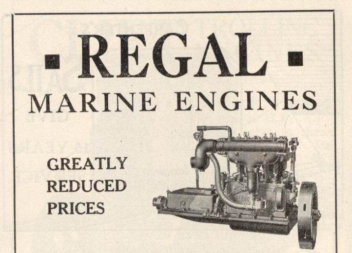
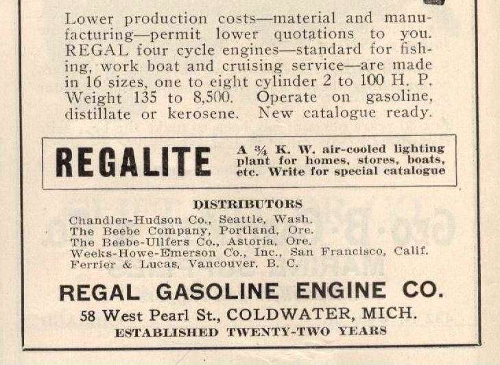
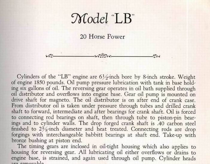
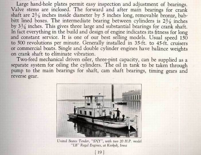
Regal
* |
bill_friday
Member
Username: bill_friday
Post Number: 16
Registered: 08-2016
| | Posted on Thursday, September 08, 2016 - 05:59 pm: |
|
Thanks Richard, These are the generally most informative of the photos, so hopefully one of the active collectors of marine engines will be able to pin it down closer. This set doesn't include a picture of the reverser, but there is a pretty good one from earlier in this forum. |
richarddurgee
Senior Member
Username: richarddurgee
Post Number: 3866
Registered: 11-2001
| | Posted on Thursday, September 08, 2016 - 08:23 pm: |
|
*
Regal 1922
* |
richarddurgee
Senior Member
Username: richarddurgee
Post Number: 3867
Registered: 11-2001
| | Posted on Thursday, September 08, 2016 - 08:38 pm: |
|
*
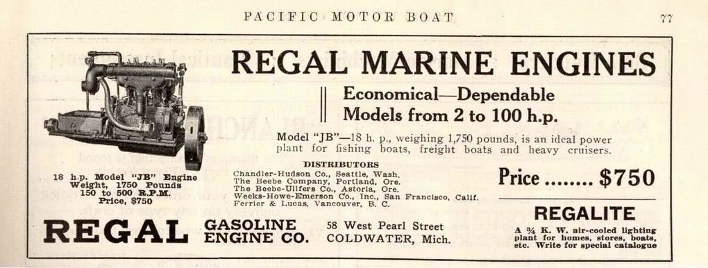
Regal model JB 1924
* |
robert
Senior Member
Username: robert
Post Number: 751
Registered: 07-2003
| | Posted on Thursday, September 08, 2016 - 09:37 pm: |
|
Pity the illustrations don't show the other side of the engine.
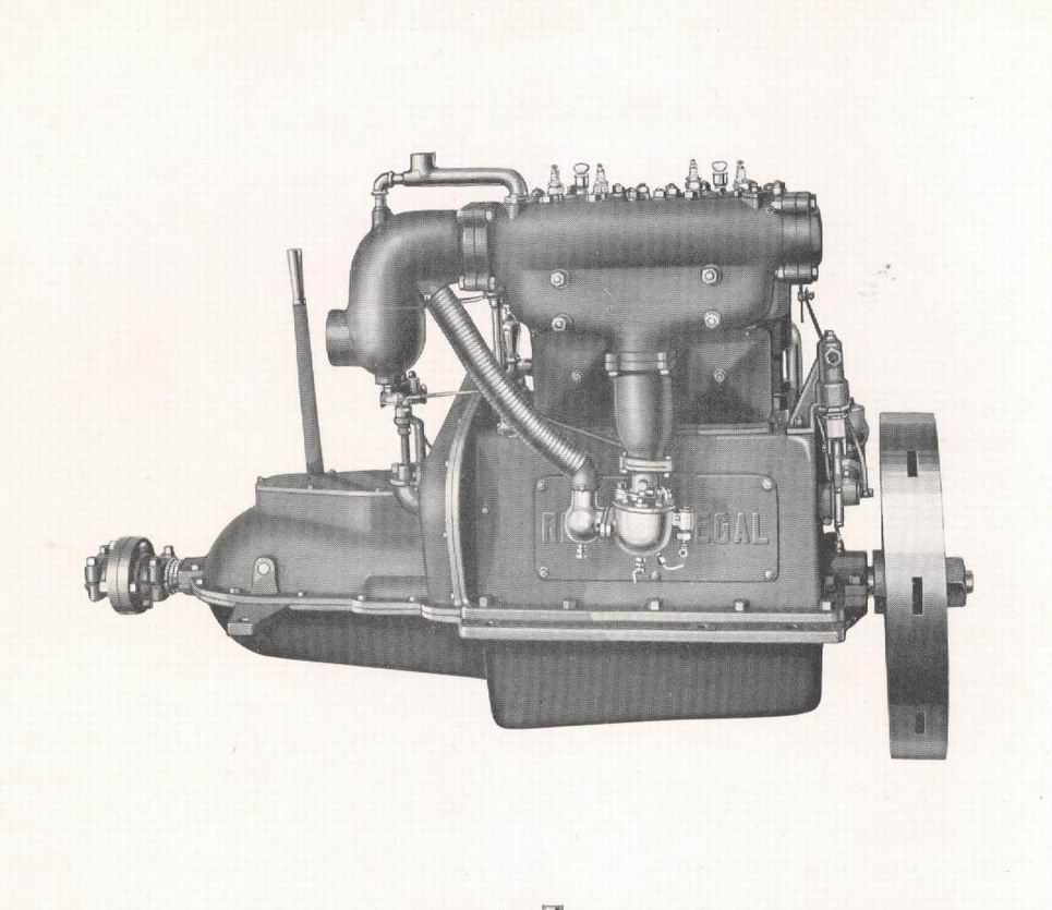
You've got a large piston pump behind the flywheel for the cooling water, driven off the end of the camshaft,so what is this gear pump for, engine oil? Looks that way with the copper tubes.
I'd be very surprised if that is not the original magneto myself, despite the second set of bolt holes in the mounting, which could be just for adjustment(?)
The advert shows a bolt on housing for a bevel gear on the end of the camshaft to drive what looks like an Atwater Kent distributor. With the water pump moved behind the cylinders?
The square gear cover would be cheaper to make than the one on this engine, so I would guess that's the earlier one. The magneto would be much more expensive than the timer as well. The advert does reference their much reduced costs.
Looks to be in fantastic shape overall. |
richarddurgee
Senior Member
Username: richarddurgee
Post Number: 3869
Registered: 11-2001
| | Posted on Thursday, September 08, 2016 - 09:37 pm: |
|
*
Regal 1925
* |
richarddurgee
Senior Member
Username: richarddurgee
Post Number: 3870
Registered: 11-2001
| | Posted on Thursday, September 08, 2016 - 09:49 pm: |
|
*
Regal Engines for 1925
* |
bill_friday
Member
Username: bill_friday
Post Number: 17
Registered: 08-2016
| | Posted on Thursday, September 08, 2016 - 11:09 pm: |
|
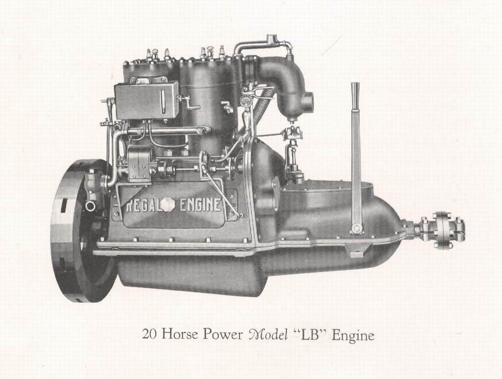
All details cited for the Model LB and shown in the pictures match our engine, except a lubricator located above the magneto. We don't have one, nor any evidence that one was ever mounted there. I'm familiar with these lubricators, as there were several manufacturers who provided them for steam engines to pump in steam oil. I've seen some on large diesel engines for lubing the bearings. Our engine, as does the one in the picture, has a gear pump on the magneto shaft, with lines running to the various bearings. The magneto shown looks very much like our Bosch, though I can't see the number of outputs. Only two will be active, with each probably connected to both spark plugs on each piston (also visible in the picture). I played with our magneto in my shop and it works perfectly to deliver sparks to the plugs at the right times. We will have to ground the other two outputs. I'll have to have it on the engine to see if the timing is correct - it didn't appear to be yesterday. Anyway, I'm confident that we have a Model LB 20HP engine. Good to know.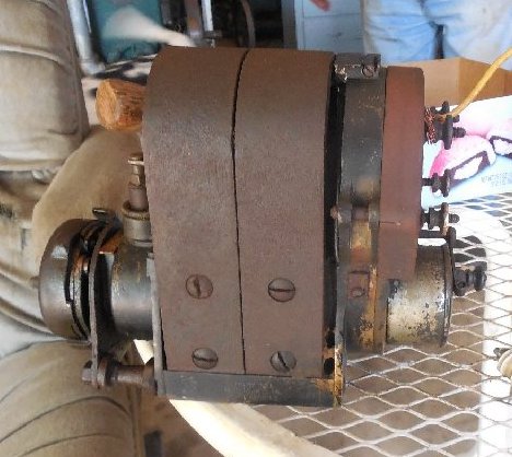 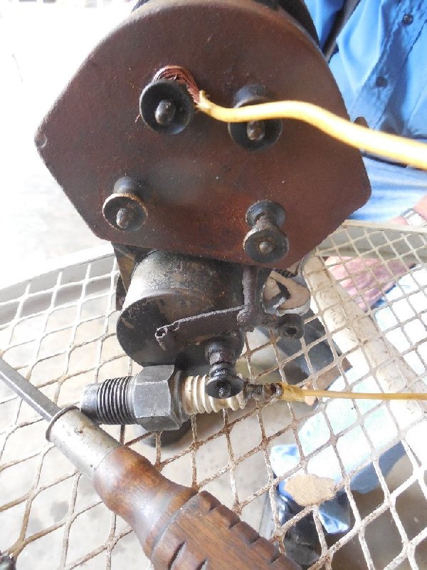 |
robert
Senior Member
Username: robert
Post Number: 755
Registered: 07-2003
| | Posted on Friday, September 09, 2016 - 10:44 am: |
|
Amazing info as usual Richard. Regal did like to change things around didn't they? AK timer to the rear this time, and three pumps driven off the end of the camshaft - must have had a good-sized bearing at that end.
The knurled nuts tell which points on the mag they were using anyway.
They certainly didn't cut any corners on these engines and the features they offered. That reverse gear and timing gear cover would be one heck of a piece of pattern making, considering how thin it had to be. No wonder they changed that out.
All it needs is a good oil filter to run for another century or two. |
bill_friday
Member
Username: bill_friday
Post Number: 18
Registered: 08-2016
| | Posted on Friday, September 09, 2016 - 11:14 am: |
|
I'm still a bit puzzled by the non-symmetrical spacing of the magneto outputs, but then the rotor in the Wico mag for my John Deere A Model tractor has a 110 degree angle between the outputs, which I've also never understood but the tractor runs great. We may need to try a few combinations of consecutive outputs to get the timing set correctly, if the cam gear can hold up that long. Two of the knurled nuts appear to have been chewed by pliers in past operation - we will try those first. There is a timing fine-adjustment lever at the bottom.
Looking at the price list above, our unit matches the $890 version - no timer, just impulse magneto. |
Huntsville
Visitor
| | Posted on Tuesday, October 18, 2016 - 03:51 pm: |
|
Bill Friday here - forgot my password. Work days have been fewer and progress slow on the Model LB Regal. We got it timed and firing at the right points but the magneto was erratic and quit completely right when we needed it - bad ground connection we think in retrospect. Today we couldn't get the sparks to come close to TDC - may have some adjustments that got lost when the oil pump and mag were removed and replaced.
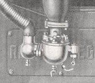
The carburetor is a Schebler DX279, shown in Richard Durgee's post on 8 Sep. I've been unable to find any documentation. It spent forty years buried in the dirt as the engine lay on its side, but being brass appears to have survived. I'd like some documentation but haven't found any. Steiner tractor lists over 500 Schebler models but none have this number The cork float broke but I think I can construct a suitable substitute.
We have probably gone as far as merits the time we are spending, what with other projects on hold. Speedboy expressed some interest in purchasing the engine, and the owner will likely let it go but I haven't asked what he might want for it.
 |