| Author |
Message |
    
rbprice
Senior Member
Username: rbprice
Post Number: 554
Registered: 11-2001

| | Posted on Sunday, October 02, 2016 - 05:16 pm: | 


|
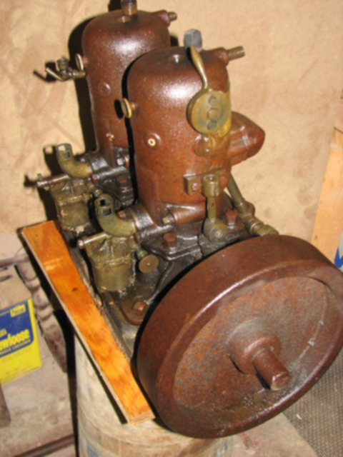
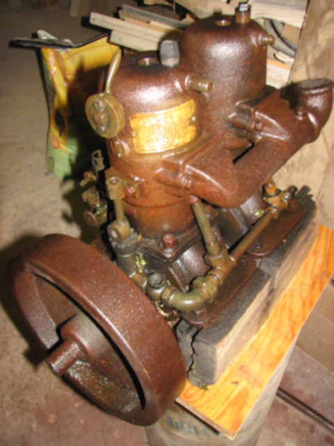
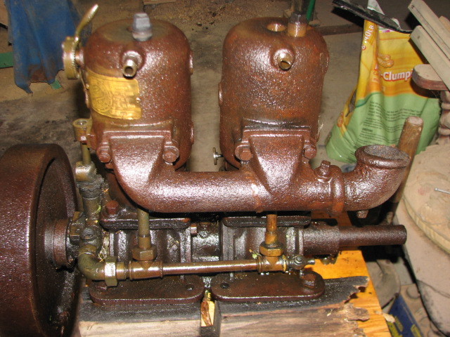
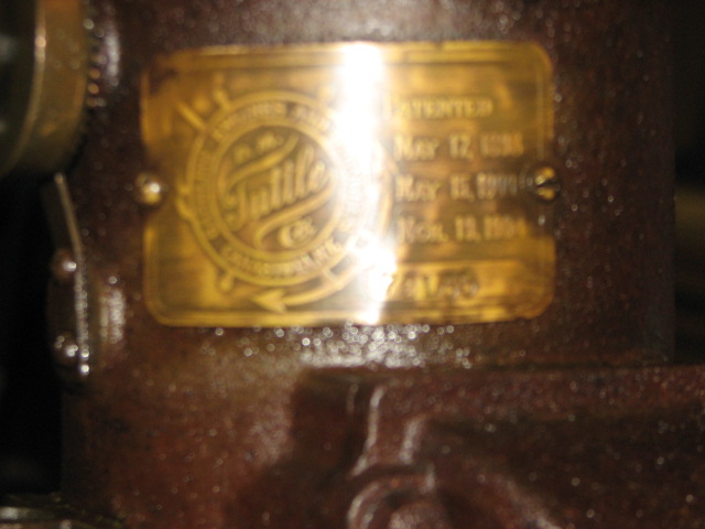
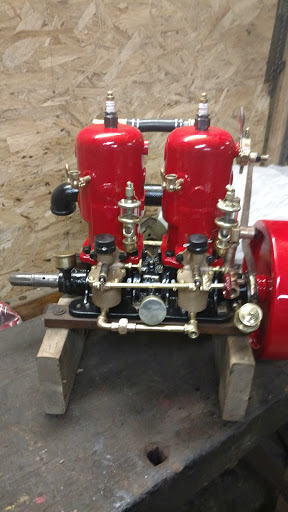
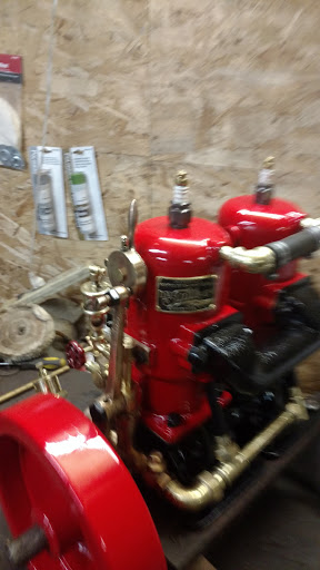
After helping a guy clean up the junkyard behind his house, he gave the the Tuttle shown below. Probably 20+ years sitting exposed to the weather but I was able to get the sparkplug holes opened and put in lots of PB Blaster and some ATF. I'll let it sit for a month and see if it is getting loose.
The patent date is 1904 but lacking any oil drip lines would indicate a post 1909/1910 date.
The pictures shows the two carburetors which I have never seen before. There seems to be a choke sleeve on the top of each inlet that would have had a rotatable sleeve on top with either slots or hole that lined up with the existing holes. Does anyone know the brand/type of those carburetors and are there any pictures available?
 |
jb_castagnos
Senior Member
Username: jb_castagnos
Post Number: 1211
Registered: 07-2002

| | Posted on Sunday, October 02, 2016 - 06:31 pm: |
|
Nice find Bob, Dick Alcock just did a restoration-resurection of a 2 and 3 cylinder Tuttle. He made patterns and cast 5 of these carbs, wish he would post the pictures on here, incredible work. He has a Tuttle boat with a 1 cylinder, now has a 2 and 3 to go along with it. Jamie had the front cylinder fo the 3 with the cas coupling on it, crank was broken in the throw. He made a crank, manifold, carbs, linkage, and primer cups. |
jb_castagnos
Senior Member
Username: jb_castagnos
Post Number: 1212
Registered: 07-2002
| | Posted on Sunday, October 02, 2016 - 06:43 pm: |
|
tried to post a link but it was wrong |
rbprice
Senior Member
Username: rbprice
Post Number: 556
Registered: 11-2001
| | Posted on Sunday, October 02, 2016 - 08:12 pm: |
|
Got your link JB - the below pictures are from Andy Schemerhorn's Tuttle that he fully restored and he has made replicas of the top of the choke.
 |
rbprice
Senior Member
Username: rbprice
Post Number: 563
Registered: 11-2001
| | Posted on Thursday, November 03, 2016 - 05:29 pm: |
|
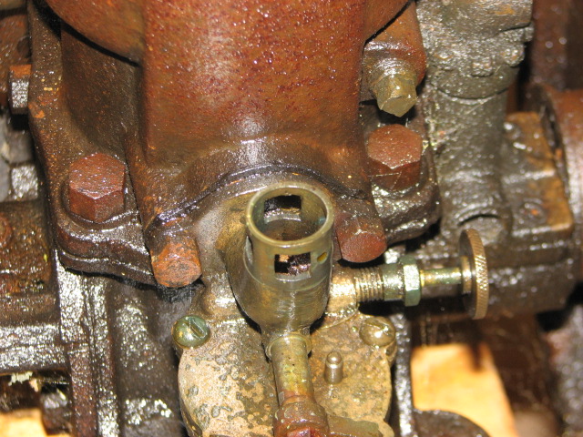
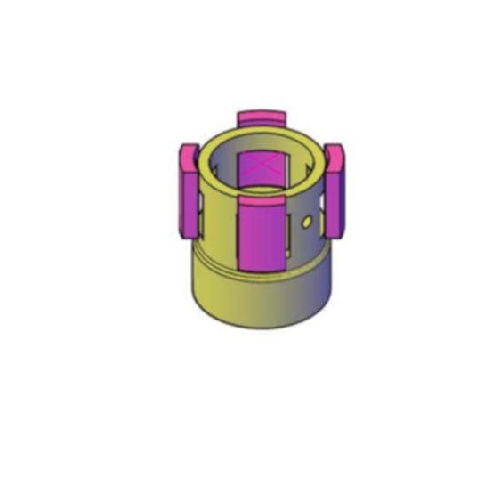
More on the question of the relationship between the cap on the intake stalk of the Tuttle carburetor and the openings in the top of the stalk.
As previously noted, there is small hole between to of the openings on the stalk and Dick Alcott says that there is a #5 screw which holds the cap to the top of the stalk. That precludes any manual rotation of the cap to control the air flow into the stalk.
That still leaves the question about the relationship of the tabs inside the cover to the four openings in the stalk. I would argue that it does not make sense that the tabs are aligned between the openings. Therefor the tabs are in a position directly over the openings but since the ID of the stalks (a machined surface not cast) and the machined OD of the top of the stalk.
That means that the air flow is going past the gap between the tabs and the openings and the screw holds the cap in that position.
Your comments are most earnestly solicited.
Thanks a bunch. |
rbprice
Senior Member
Username: rbprice
Post Number: 564
Registered: 11-2001
| | Posted on Thursday, November 03, 2016 - 08:06 pm: |
|
Here's a cartoon of the stalk with the four tabs arrayed around the outside. The newly cast cap would be machined to be a 0.025 clearance on the OD of the stalk. And the existing hole in the stalk would use a screw to hold the cap in place.
 |
jb_castagnos
Senior Member
Username: jb_castagnos
Post Number: 1241
Registered: 07-2002
| | Posted on Friday, November 04, 2016 - 07:41 pm: |
|
Bob, from the drawings I would say the cap is an air adjustment to help balance the carburetors. |
rbprice
Senior Member
Username: rbprice
Post Number: 565
Registered: 11-2001
| | Posted on Friday, November 04, 2016 - 08:16 pm: |
|
I would agree JB if it were possible to rotate the cap so that one could "throttle" the air flow through the little "windows" But since the cap is fastened to the stalk with a screw and cannot be rotated and locked in some alternate position, I think the cap mostly functions as a labyrinth to keep large pieces of debris from entering the carburetor while still allowing a sufficient air flow to the engine.
As always, your comments are earnestly solicited. |
giii
Member
Username: giii
Post Number: 22
Registered: 04-2010
| | Posted on Friday, November 04, 2016 - 09:57 pm: |
|
My Waterloo farm engine has a cup over the air inlet to adjust the air flow that is also held by a screw in the side that goes through a slot in the cup itself. Could this be similar?
George |
rbprice
Senior Member
Username: rbprice
Post Number: 566
Registered: 11-2001
| | Posted on Saturday, November 05, 2016 - 08:12 am: |
|
I wish it were so George. It would be easy to mill a slot in the Cap so one could make it rotate but there is no radial slot. It is a strange arrangement. |