|
| J.B.'s Rod Bearing Pouring and Machin... |
| Author |
Message |
    
richarddurgee
Senior Member
Username: richarddurgee
Post Number: 1157
Registered: 11-2001

| | Posted on Sunday, June 18, 2006 - 02:03 pm: | 


|
J.B.'s Photos
Rod bearing pouring and machining process
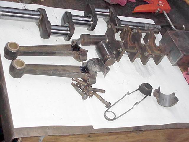
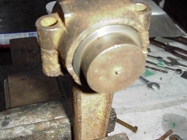
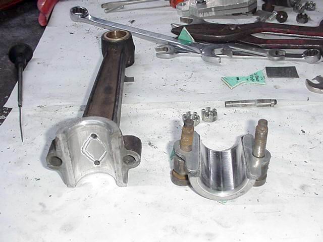
1.Damaged Rod
2.Starting
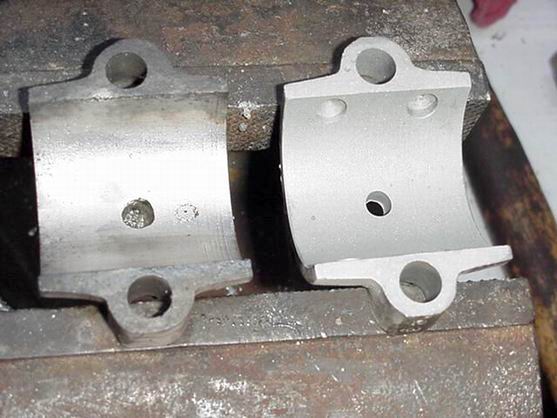
3. Tinned Cap
4.Centering Pin
5.Pin in Place
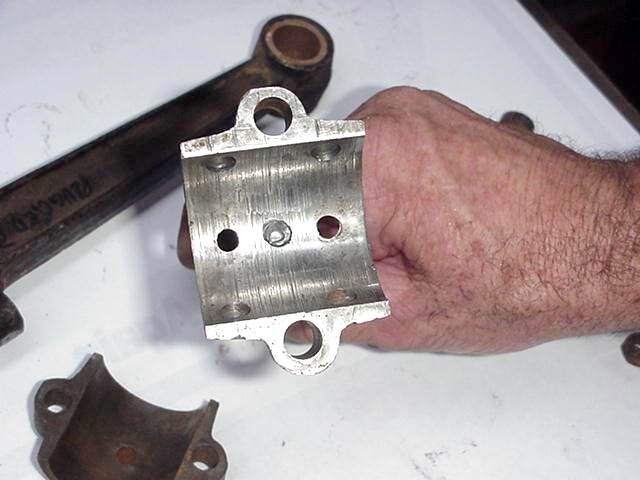
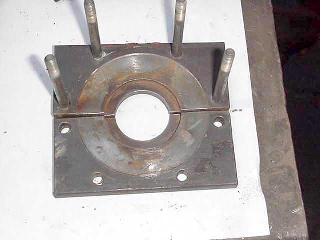
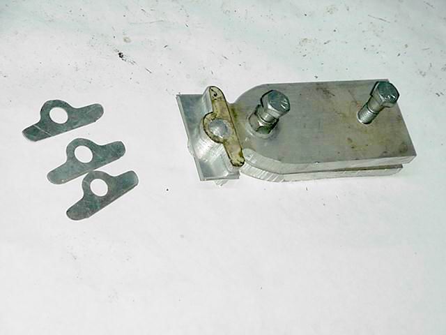
6.Saddle Plates
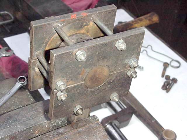
7.Plates Installed
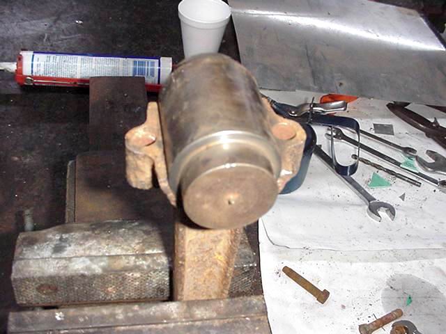
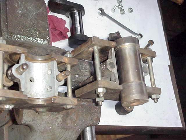
8.Shaft Installed
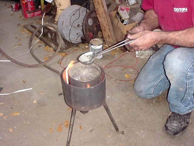
9.Pre Heating
10.Skimming Dross
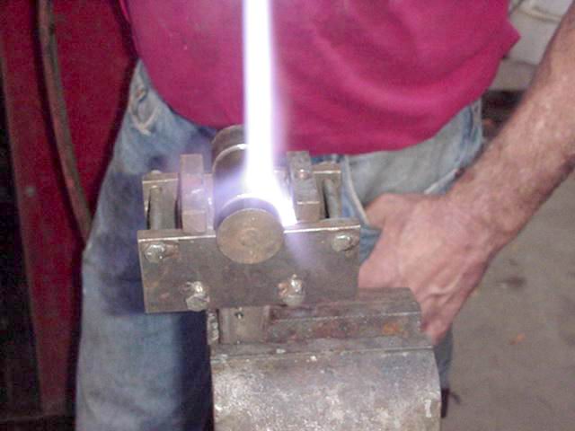
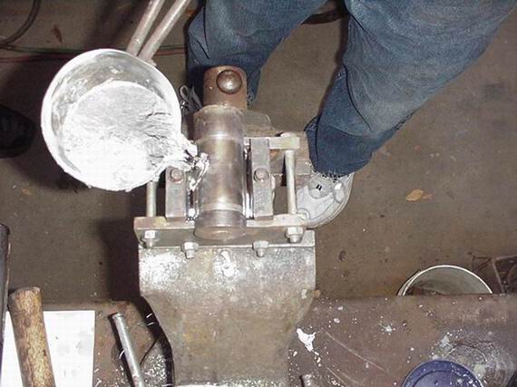
11.Pouring
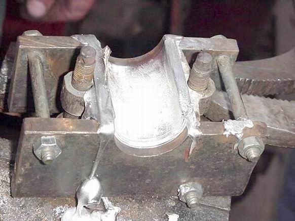
12.Poured
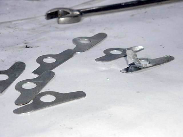
13.Shim Jig
14.Peelaway Shims
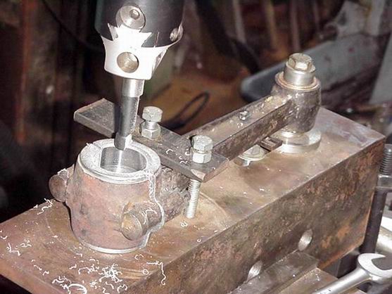
15.Rod Boring
16.Finished bearing
17.Testing Fit
 |
jb_castagnos
Senior Member
Username: jb_castagnos
Post Number: 143
Registered: 07-2002
| | Posted on Monday, June 19, 2006 - 10:05 pm: |
|
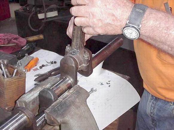
We poured rod bearings for David Prejean Saturday,took some photos to show the procedure. L-A and Nadler used an insert type bearing, I made a mold for these but soon realized that most of the rods were no longer a true machined bore. The rod in the first picture was run against the crank without a bearing. The rods and caps are blasted and tinned with an acid core paste to help the bearing "stick". The centering pin is a pin machined to fit the OD of the rod and stepped to the size of the rod journal, in this case 1 5/8" with 1 3/8" on each side. The saddle plates are two pieces of flat bar, they were placed back to back on the flat in the 4 jaw chuck, the edges faced off, and then they were tacked togehter to form a square plate as seen in the 6th picture. A 1 3/8' hole was bored, then it was counter bored to form the flange area of the rod bearing. It's not critical that the hole be dead center of the split. The rod cap is tightened against the centering pin and the saddle plates are tightened in place against the pin, the gap between the cap and rod with the pin in place is the amount of shim you should start with. The centering pin is removed and the shaft is inserted, this crank is undersized so the shaft is turned in the middle. If you didn't want to bore the finished bearing the shaft would be turned to match the crank, in this case it was smaller. All holes in the rod were sealed with rtv silicone, no need to wait for it to dry. One of the most important steps to pouring babbit is to preheat the parts, have the babbit hot enough, and pour it fast. If you pour it slow, it will freeze before going all the way around. I use two pieces of square stock on the sides of the rod to give a better pouring target and to give the babbit some head pressure, you also have a reserve in case it leaks a little or shrinks. The shim jig holds a stack of shim material, it's drilled then routed with a pattern tracing bit in the router. These are peel away shims, .002" per layer, Dickie Gibbens introduced me to these, used in the helicopter industry. McMaster Carr has sheets available. The rod is bolted together with the shims, placed in the boring jig, centered and squared up, and bored to size. I usually leave .003 to .004" clearance. I learned the hard way not to build them to tight, was having bearing failures on a good fitting bearing when I realized that most of the engines taken apart were worn and sloppy but kept running. I think 2 cycles experience the same thing as compressors that lose a check valve. If a compressor loses a check valve and continues running, it usually burns a rod brg and or wrist pin. The problem is known as non rod reversal, it stays loaded one way and doesn't allow oil under the bearing. Two cycles are always loaded in one direction, with out a little play the bearing is easily starved. I use a 1/8" radius router bit to radius the ends of the bearing. David ended up pouring three of the four bearings, did most of the filing and fitting and routing, he was a good student. |
richarddurgee
Senior Member
Username: richarddurgee
Post Number: 1161
Registered: 11-2001
| | Posted on Tuesday, June 20, 2006 - 02:43 pm: |
|
JB
I want to say that I appreciate your technical and machining abilities and the extra effort you go to photgraph the almost lost processes of restoring these old marine engines and sharing it here on line, I go over the photos often to really understand how its done ! I have now figured out how to get this quality of work or (art form) on my Lockwoods--
Step 1. Take connecting rods, pistons , cyls,crankshafts, crankcases etc and wrap them very well and put in box .
Step 2. Fill out and attach shipping label to
Donaldsonville, LA % JB
Great stuff Thanks Richard |
peterogborne
Senior Member
Username: peterogborne
Post Number: 148
Registered: 09-2002
| | Posted on Wednesday, June 21, 2006 - 07:28 am: |
|
I also was impressed with the whole procedure,the photos were great .The shim is interesting ,what is the material? |
jb_castagnos
Senior Member
Username: jb_castagnos
Post Number: 146
Registered: 07-2002
| | Posted on Wednesday, June 21, 2006 - 09:18 am: |
|
Thanks Richard & Peter.
Go to http://www.mcmaster.com/ in the shearch box enter laminated shims. I use the aluminum .002", it's easy to cut and trim with the router. |
jcurran
New member
Username: jcurran
Post Number: 1
Registered: 02-2023
| | Posted on Wednesday, February 08, 2023 - 09:54 am: |
|
Excellent presentation. The best I've seen so far! I have a broken babbit on my 3 HP St. Lawrence. One question what is the proceedure for tinning the cap? Thanks again |
jim_parrott
Senior Member
Username: jim_parrott
Post Number: 221
Registered: 06-2009
| | Posted on Tuesday, February 14, 2023 - 01:43 pm: |
|
Jeff,
JB states that he used acid core solder paste for tinning the caps. Separate flux and solder can be used. Just heat up to have a thin coat of solder. Most caps have shallow holes drilled in them that will hold the without tinning.
Jim |
|
|
|


|