| Author |
Message |
    
narrabay
Member
Username: narrabay
Post Number: 28
Registered: 05-2016
| | Posted on Monday, March 19, 2018 - 07:51 pm: | 


|
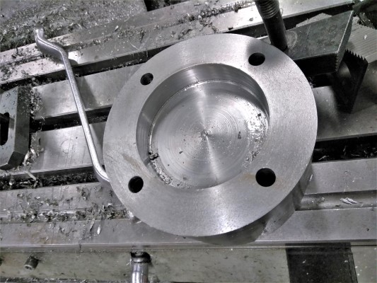
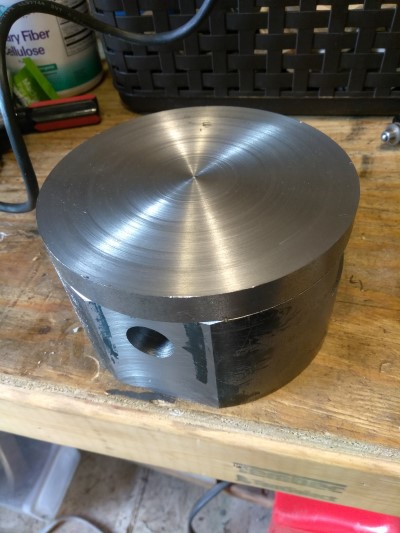
I have no idea how well this will work out but today as a side project I started making a new YT cylinder head. So far have the combustion chamber machined and the head bolt holes drilled, and they align perfectly. I do plan to slightly enlarge the bolt holes by 1/64 just so the head drops right on very slightly loosely.
This effort may take some time to complete as I tend to work slowly. Hopefully it is a success and that posting the progress here will help someone someplace down the line.
 |
narrabay
Member
Username: narrabay
Post Number: 29
Registered: 05-2016
| | Posted on Monday, March 19, 2018 - 07:53 pm: |
|
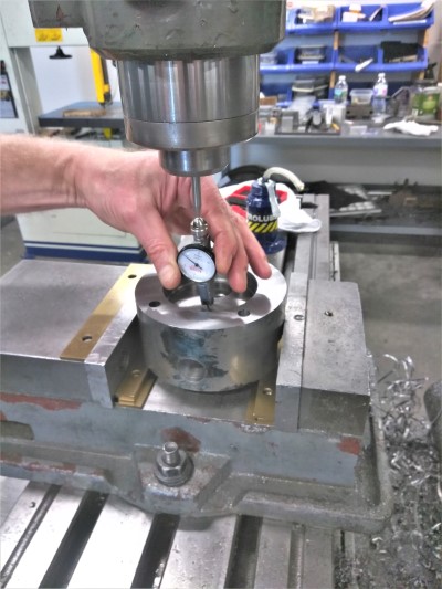
Lining up the bolt holes using a Bridgeport and an old head someone graciously donated as a template:
 |
narrabay
Member
Username: narrabay
Post Number: 30
Registered: 05-2016
| | Posted on Thursday, March 22, 2018 - 01:15 am: |
|
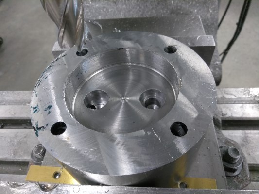
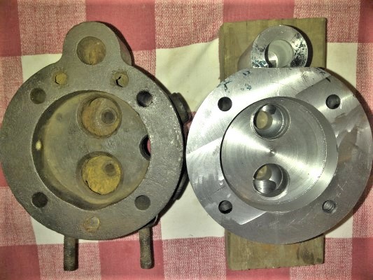
Combustion chamber and head bolt holes.
 |
narrabay
Advanced Member
Username: narrabay
Post Number: 31
Registered: 05-2016
| | Posted on Thursday, March 22, 2018 - 06:29 pm: |
|
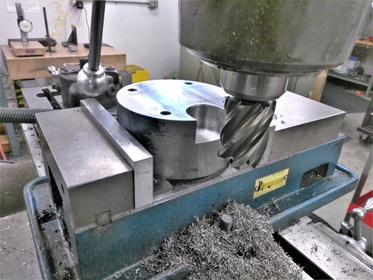
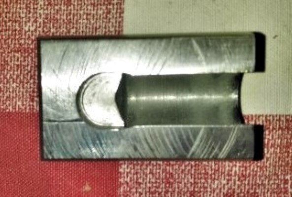
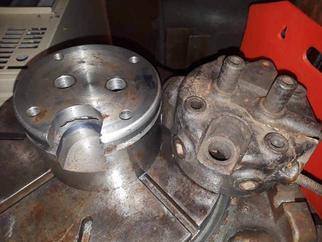
I cut the spark plug pocket today. Going to drill it to .504" then tap it for a modern size plug, 14x1.25mm - same 3/4" reach.
This part is the body of the head 1/2" shorter. Planning to make a top cover 1/2" thick. This will allow for milling out water jacket areas. Final height will allow for gasket, and valve guides should be able to seal with o-rings in machined grooves, where they pass through the top cover.
 |
narrabay
Advanced Member
Username: narrabay
Post Number: 32
Registered: 05-2016
| | Posted on Friday, March 23, 2018 - 03:57 pm: |
|
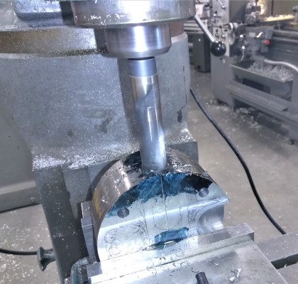
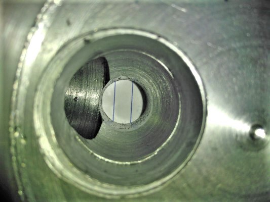
Started to drill the intake and exhaust passages today. Intake 3/4" diameter because thats all it is on the old head at the entry point. The exhaust I could only get to 7/8" due to the amount of material I wanted to leave. But I may use an end mill to shave the sizes and make it oval for more exhaust passage area. (I cant go up and down any more but left and right is possible). Only went in 1.5" to leave material for a smoothed, rounded 90 degree transition from passage to valve.
next week I will mill the exhaust valve pockets and guide holes in one part holding operation each so they are concentric. and have a 1" ball end mill coming to make the transition smooth like the original.
Having no idea what valve this uses, I wil try to find something common and of the right stem length as that the least negotiable dimension. I'm thinking just over 1" diameter valves (opening will be 1" then need the chamfer), and can make the guides any ID for whatever stem diameter. That means fining a valve with the right stem length and a 1" diameter valve.
any suggestions where to look up valves by dimension?
 |
billschaller
Senior Member
Username: billschaller
Post Number: 694
Registered: 12-2003

| | Posted on Sunday, March 25, 2018 - 07:16 pm: |
|
Good luck. looks like an interesting project. when I retire in 3 months, I hope to start working on some of my projects. If you can't find a valve, making one will be a whole lot easier than the rest of the head. |
narrabay
Advanced Member
Username: narrabay
Post Number: 33
Registered: 05-2016
| | Posted on Monday, March 26, 2018 - 12:33 pm: |
|
Thanks Bill, it's very relaxing. Wish I could retire, but that's a few more years for me. I think the hard part will be cutting in the water jackets around everything else. Only saving grace is that being 1018 steel, this can be easily welded should a miscalculation happen.
Today, worked on the valve pockets and passages, as well as the side piece for the intake runner. Another guy in the shop with a lot more experience solved that by suggesting to mill the side of the head flat, turn a round 1.5" piece with the 3/4" passage in it, and mill one side of that, and mig weld it on. So we worked together on that. Being new at machining, it really helps to get help and ideas like that one.
 |
narrabay
Advanced Member
Username: narrabay
Post Number: 34
Registered: 05-2016
| | Posted on Monday, March 26, 2018 - 07:29 pm: |
|
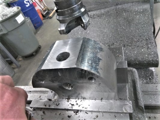
A little more progress, made the intake vertical runner feature which is on the side of the head, which will be mig welded on, and filleted along the edges to match the original. Drilled out the valve guide holes. Also, the 1" ball end mill showed up today so I rounded the transition where the port meets the valve pocket. Will do some hand work with a die grinder to smooth it all out. The messy top of the valve openings is just a tool holding problem I had with a collet that adapts a 1" shank end mill. It doesn't hold it well and I suggested it go into the scrap bin! The combustion chamber needs to go about .050" deeper anyway plus the valve seat formed so that will all clean up.
 |
miro
Senior Member
Username: miro
Post Number: 961
Registered: 11-2001

| | Posted on Thursday, March 29, 2018 - 08:19 am: |
|
Not knowing the geography of the eastern USA seaboard all that well, I think that a lot of folks would love to see the work on the head at the Calvert Show in early May.
Plus we'll have the opportunity to share our experiences and break bread together ( and perhaps an adult beverage or two)
Miro |
narrabay
Advanced Member
Username: narrabay
Post Number: 35
Registered: 05-2016
| | Posted on Thursday, March 29, 2018 - 10:46 pm: |
|
hi miro, thanks for the idea. I just looked it up and it would be about 9 hours drive each way. I wont have any vacation by then. However, Mystic is Aug 18-19 and is very close (45 mins) and by then either the dispro boat will be done, or mostly done and I could tow it there easily. So maybe thats a better option for this year.
As to the cyl head, I need to get back into the shop but don't know when I can. Eventually it's in the works to obtain an old Bridgeport for home but that depends on a few things like how the job goes and finding one cheap enough that is good enough. One way or another though.
I did order a set of valves with the right stem diameter and length I can machine the valve heads so thats solved. |
narrabay
Advanced Member
Username: narrabay
Post Number: 36
Registered: 05-2016
| | Posted on Sunday, April 01, 2018 - 11:21 am: |
|
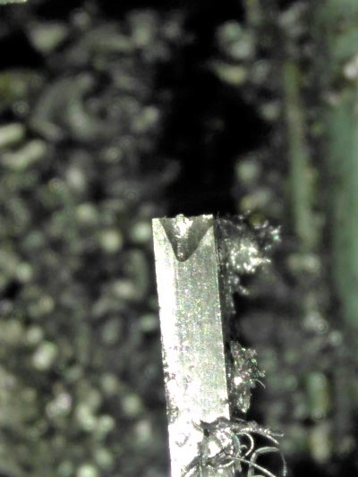
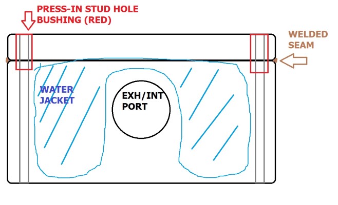
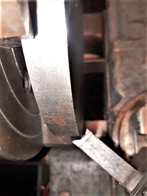
Had some trouble parting the top cover, the tool was chattering. So I saw a trick to notch the tool and it worked really well. Got about halfway in, reaching limit of tool, and finishing that cut with a hack saw. Will face turn the cut side flat and start laying out the holes starting with the head stud holes. Then drill and tap the valve stanchion holes, and the water outlet which I noticed is above the exhaust port (makes sense, get the hottest water out). On the underside, will relieve it enough to assure good water flow especially around that exhaust passage. As far as sealing the stud holes between top and bottom, I will have pressed in bushings there with locktite (which probably really wont be needed).
As to whether to bolt this on with a gasket and use o-rings to seal where the valve guides come through, or chamfer it and weld it and grind the weld flat, not decided. The weld would be cleaner like original, a bolted solution can be reopened. But thats probably not even necessary anyway. May end up welding this on, radius the top edge like original and make it look that much more like Palmer intended.
 |
narrabay
Advanced Member
Username: narrabay
Post Number: 37
Registered: 05-2016
| | Posted on Sunday, April 01, 2018 - 12:26 pm: |
|
Graphic on sealing the stud passage between the top and bottom since that seam 1/2" down inside a 3/8" diameter hole cant be easily welded. The water jacket is not that big on both sides as the spark plug indent is on one side but this gives the idea on the stud sealing bushings.
 |
jb_castagnos
Senior Member
Username: jb_castagnos
Post Number: 1369
Registered: 07-2002

| | Posted on Sunday, April 01, 2018 - 12:39 pm: |
|
My thoughts were to mill the top off ,a spot facer in the bolt holes would have left a shoulder sticking up., mill away the rest, make a plate to fit over the shoulders. after milling the water passages a new cover could have been fabricated, either silver soldered or siliconed into place. |
narrabay
Advanced Member
Username: narrabay
Post Number: 38
Registered: 05-2016
| | Posted on Sunday, April 01, 2018 - 05:49 pm: |
|
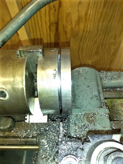
And a little Easter relaxation, finish the top cover to .010" over, for now.
 |
narrabay
Advanced Member
Username: narrabay
Post Number: 41
Registered: 05-2016
| | Posted on Thursday, July 26, 2018 - 07:34 pm: |
|
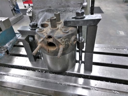
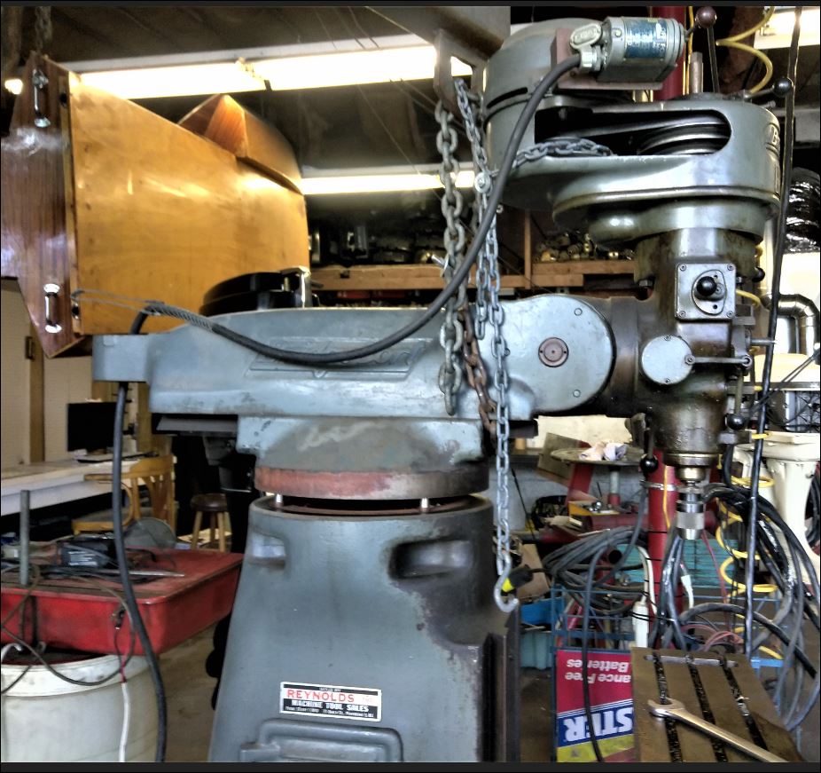
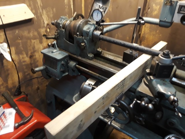
Instead of being a guest back at the shop I learned in, decided to hunt down a Bridgeport Mill of my own. After months, finally found a J-head in decent shape for a good price. This is a pic of separating the top off of it. Despite only finding doom and gloom about how hard it would be to disassemble and move, the top came off and the knee (with table) came off inside of ten minutes, making three almost equal weight sections of 500-700 lbs. The second slightly slack chain through the pulley area is crucial in case the whole section decided to turn over, as the main chain is below the center of gravity.
So, we should be seeing the water jackets being machined out fairly soon, once I get this machine up and running.
 |
ned_l
Senior Member
Username: ned_l
Post Number: 173
Registered: 08-2012
| | Posted on Thursday, August 02, 2018 - 05:17 pm: |
|
Nice! I've had a couple of opportunities to pick one up over the years, .... problem is I just don't have the space for it. ... And, there is a full machine shop where I can work that I can use anytime, .. and ... my neighbor right across the street has one. So why do I really need it?? |
narrabay
Advanced Member
Username: narrabay
Post Number: 42
Registered: 05-2016
| | Posted on Friday, September 21, 2018 - 12:05 am: |
|
Ned, mine is still in three pieces, need to add onto the shed to make a place for it!
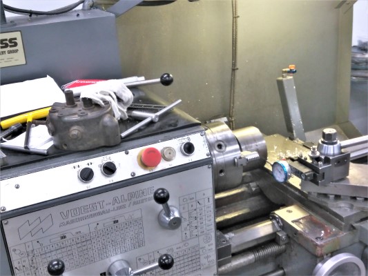
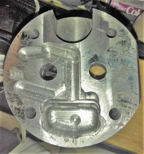
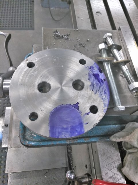
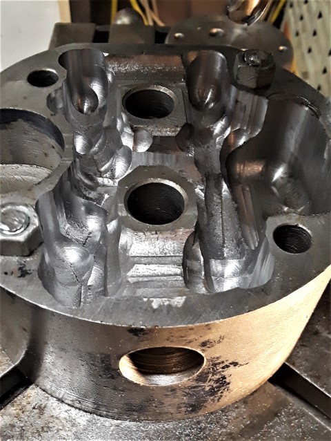
This week I was invited back to the shop I trained in as it was slow, and got to milling out the water jackets.
just not sure just how much room is needed, how thick the walls can be etc. So far I have left >3/8 thickness on the combustion chamber ceiling, and about 1/4" on the side wall. By the time I keep clear of head bolt holes, intake and exhaust runners etc, and the spark plug notch, there isnt much left to remove.
I hoping that this is a low tension engine with no thermostat will help. And I am trying to get coolant passages around the exhaust port as much as I can but in any case there is going to be much more metal left than with the original cast piece.
The rotary table was very loose and old, and that shows in the horrendous machining. I eventually figured out how to use the brake lever somewhat and adjust tool speed to get it to sort of behave. This is a water jacket and no one will see it, and the extra "features" etc just add surface area right? :/
 |
narrabay
Advanced Member
Username: narrabay
Post Number: 43
Registered: 05-2016
| | Posted on Friday, September 21, 2018 - 12:09 am: |
|
 |
narrabay
Advanced Member
Username: narrabay
Post Number: 44
Registered: 05-2016
| | Posted on Friday, September 21, 2018 - 01:06 pm: |
|
Today worked on the top cover, lay out the four bolt holes and the two valve guide hols and the spark plug relief, and get those all cut...
 |
narrabay
Advanced Member
Username: narrabay
Post Number: 45
Registered: 05-2016
| | Posted on Friday, September 21, 2018 - 01:07 pm: |
|
 |
narrabay
Advanced Member
Username: narrabay
Post Number: 48
Registered: 05-2016
| | Posted on Saturday, January 05, 2019 - 10:48 pm: |
|
just a quick update for anyone following this, waiting to make some space for the Bridgeport. Turns out much easier to buy an old machine than to create space for it. meanwhile this cyl head sits next to my recliner as a reminder. Same for the Dispro project, it's ready to move along when the Bridgeport and a few other priorities are out of the way. Happy 2019 |
narrabay2
Member
Username: narrabay2
Post Number: 5
Registered: 10-2019
| | Posted on Friday, November 29, 2019 - 12:45 pm: |
|
Another quick update, I have just finally finished installing and test run the Bridgeport Mill. Also picked up a good 11" rotary table for it. Hopefully can get onto finishing the water jacket work that was suspended a year ago!
Also, had to establish a new nickname (narrabay2) because went to change my email and the confirmation code never came through after several tries and that put it stuck in a loop. Emailed the admin with no result (mailbox full). Hopefully this wonderful site will stay up, lot of good information here it is like an encyclopedia. Just throwing that out there in case he sees it here, and can fix. |
chris_spring
Advanced Member
Username: chris_spring
Post Number: 35
Registered: 02-2019
| | Posted on Friday, November 29, 2019 - 01:34 pm: |
|
Had the same issue wrt email and admin. Had to re-register.PITA. That said, although at times the site is not very active, it remains a valuable resource. So I keep hanging around.
Cheers! |
ned_l
Senior Member
Username: ned_l
Post Number: 202
Registered: 08-2012
| | Posted on Friday, December 13, 2019 - 12:23 pm: |
|
Yes, ...can be a bit slow here.
Glad to see you are back at it with the head, I'll look forward to seeing it next year at Mystic. |
narrabay2
Member
Username: narrabay2
Post Number: 6
Registered: 10-2019
| | Posted on Saturday, December 28, 2019 - 07:59 pm: |
|
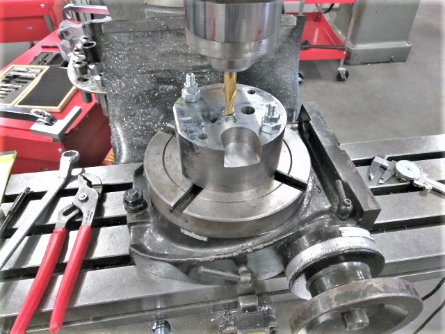
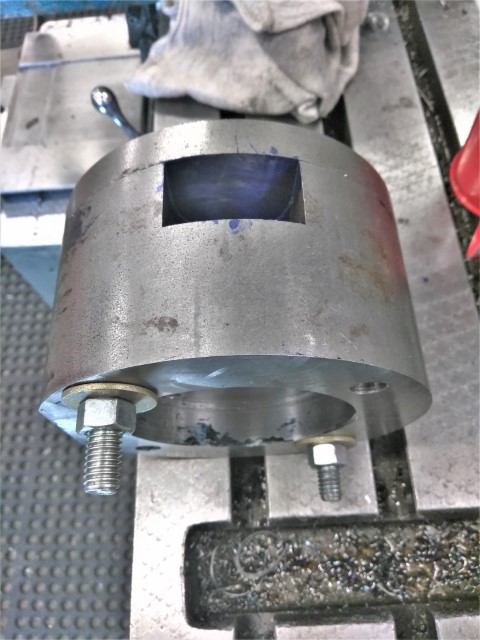
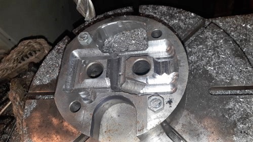
OK, FINALLY, have my new old Bridgeport up and running (a year and a half effort), as of last night, and already mounted the YT 1 head and working on the water jackets some more. The idea is that no wall should be less than approx .250"
The wall around the spark plug pocket is thinner at the top than I like so I will fill the inside of the rim with mig weld and re-machine that.
This is hand work and not particularly scientific or precise, just hoping to make room enough for sufficient cooling to take place then we're home free...
 |
narrabay2
Member
Username: narrabay2
Post Number: 7
Registered: 10-2019
| | Posted on Saturday, December 28, 2019 - 08:15 pm: |
|
OK, FINALLY, have my new old Bridgeport up and running (a year and a half effort), as of last night, and already mounted the YT 1 head and working on the water jackets some more. The idea is that no wall should be less than approx .250"
The wall around the spark plug pocket is thinner at the top than I like so I will fill the inside of the rim with mig weld and re-machine that.
This is hand work and not particularly scientific or precise, just hoping to make room enough for sufficient cooling to take place then we're home free...
|
narrabay2
Member
Username: narrabay2
Post Number: 8
Registered: 10-2019
| | Posted on Saturday, December 28, 2019 - 08:15 pm: |
|
OK, FINALLY, have my new old Bridgeport up and running, as of last night, and already mounted the YT 1 head and working on the water jackets some more. The idea is that no wall should be less than approx .250"
The wall around the spark plug pocket is thinner at the top than I like so I will fill the inside of the rim with mig weld and re-machine that.
This is hand work and not particularly scientific or precise, just hoping to make room enough for sufficient cooling to take place then we're home free... |
narrabay2
Member
Username: narrabay2
Post Number: 9
Registered: 10-2019
| | Posted on Saturday, December 28, 2019 - 08:19 pm: |
|
OK, FINALLY, have my new old Bridgeport up and running, as of last night, and already mounted the YT 1 head and working on the water jackets some more. The idea is that no wall should be less than approx .250"
The wall around the spark plug pocket is thinner at the top than I like so I will fill the inside of the rim with mig weld and re-machine that.
This is hand work and not particularly scientific or precise, just hoping to make room enough for sufficient cooling to take place then we're home free...
 |
narrabay2
Member
Username: narrabay2
Post Number: 10
Registered: 10-2019
| | Posted on Saturday, December 28, 2019 - 08:38 pm: |
|
OK, FINALLY, have my new old Bridgeport up and running, as of last night, and already mounted the YT 1 head and working on the water jackets some more. The idea is that no wall should be less than approx .250"
The wall around the spark plug pocket is thinner at the top than I like so I will fill the inside of the rim with mig weld and re-machine that.
This is hand work and not particularly scientific or precise, just hoping to make room enough for sufficient cooling to take place then we're home free...
|
narrabay2
Member
Username: narrabay2
Post Number: 11
Registered: 10-2019
| | Posted on Saturday, December 28, 2019 - 08:55 pm: |
|
OK, FINALLY, have my new old Bridgeport up and running, as of last night, and already mounted the YT 1 head and working on the water jackets some more. The idea is that no wall should be less than approx .250"
The wall around the spark plug pocket is thinner at the top than I like so I will fill the inside of the rim with mig weld and re-machine that.
This is hand work and not particularly scientific or precise, just hoping to make room enough for sufficient cooling to take place then we're home free... |
narrabay2
Member
Username: narrabay2
Post Number: 12
Registered: 10-2019
| | Posted on Saturday, December 28, 2019 - 08:56 pm: |
|
Picture
 |
narrabay2
Member
Username: narrabay2
Post Number: 13
Registered: 10-2019
| | Posted on Saturday, December 28, 2019 - 09:04 pm: |
|
this site is now not letting post pics. |
narrabay2
Member
Username: narrabay2
Post Number: 14
Registered: 10-2019
| | Posted on Sunday, December 29, 2019 - 01:18 am: |
|
this site is now not letting post pics. |
narrabay2
Member
Username: narrabay2
Post Number: 15
Registered: 10-2019
| | Posted on Sunday, December 29, 2019 - 01:30 am: |
|
now the pic has posted, go figure!
not to mention multiple repeat posts which all appeared later. |
ernie
Senior Member
Username: ernie
Post Number: 2561
Registered: 01-2002
| | Posted on Wednesday, January 01, 2020 - 02:56 pm: |
|
Test
 |
ernie
Senior Member
Username: ernie
Post Number: 2562
Registered: 01-2002
| | Posted on Wednesday, January 01, 2020 - 03:03 pm: |
|
Tested
Chris maybe you need to check your browser settings.
Worked fine for me, as you can see I took one of your pics and saved it to my desktop. Then re posted it.
As to e-mail problems and registration I have had the same screen name and registration for 18 years. Never an issue. Once again these problems might be related to your browser settings, or multiple screen names. Over the years I have used a ton of IE versions, Lots of Fire Fox versions and a few chrome. Currently Fire Fox 70.0.1
Hope this helps
Ernie |
narrabay2
Member
Username: narrabay2
Post Number: 17
Registered: 10-2019
| | Posted on Thursday, January 02, 2020 - 11:55 pm: |
|
thanks. as another user posted above, when I changed my email in an attempt to get notifications working, I never got the confirmation email, and it also wouldnt let me go back . same issue as the other user above. requests for assistance to admin received "mailbox full" reply. I've been a member in good standing on a dozen specialty forums some going back 20 years (hard to believe!) and never couldnt reach an admin.
So had no choice but to just make a new name. with that new name I tried to post the pic, and the system showed an error so i retried a couple times, nothing. then later, they all appeared. There is a 30 min limit on deleting posts here, so only an admin can delete the duplicates now.
but all seems good now. just in case it is my browser somehow, I'll clear the cache etc.
__________________
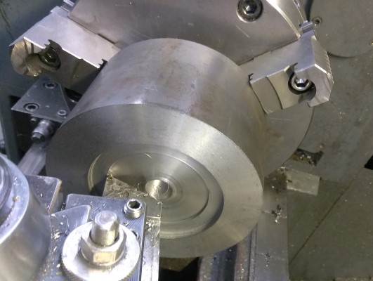
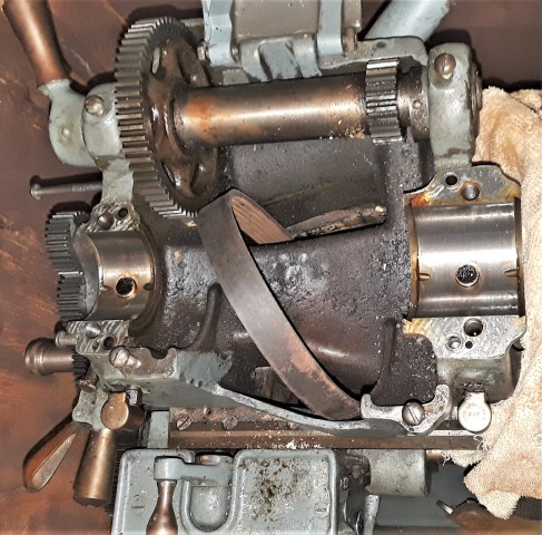
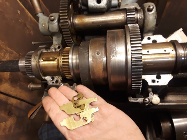
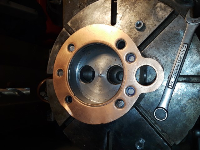
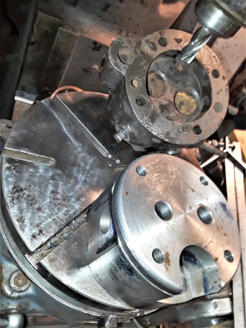
As for todays update, I went to chuck the cylinder head's top piece in the lathe and it wouldnt fit in the 3 jaw, and the bigger 4 jaw doesnt have reversible jaws. soooooo.... no problemo, just order a larger 8" chuck with reversible jaws. only, my south bend heavy 10r has the rare smaller spindle with a 1-7/8" thread diameter. fortunately, the bigger 2-1/4" snout spindle is a direct swap. so I found one locally and spent the last couple days carefully extracting the old spindle and pulling the gears etc off of it.
despite being tempted to completely strip, degrease, inspect, and repaint the lathe, decided to just install the spindle for now and restore the machine later. in fact the bridgeport head is higher on the list for teardown and reassemble etc.
Here is the dirty, greasy lathe headstock minus the spindle. As soon as it goes back together, will get an 8" 4-jaw chuck on order and get back to adding a radius to the top cover for this YT cylinder head that will match the original.
 |
miro
Senior Member
Username: miro
Post Number: 1065
Registered: 11-2001
| | Posted on Sunday, January 05, 2020 - 01:27 pm: |
|
I really admire the lengths that you have traveled to get this head done-
Similar to Ernie, I've been using the same ID on this web site / forum, since 1998 or 1999, and seems to still be working OK.
Thank you Andrew M for taking care of it all.
Miro |
narrabay2
Member
Username: narrabay2
Post Number: 18
Registered: 10-2019
| | Posted on Monday, January 06, 2020 - 01:41 pm: |
|
Thanks Miro. Not criticizing, yes this is a really great resource, just sharing my experience. Try changing your email address and you'll get stuck too. Reaching out gets a "mailbox full" reply. Thats why had to create a total new acct, same as the other user above. I hope this very unique and valuable repository can someday come under a library or museum for perpetuity, that's how good it is and Andrew is owed debt of gratitude for its existence.
As to these lengths, yeah!!!! I went to chuck the top cover to make the corner radius like a YT head, and wouldnt fit. Went to buy larger chuck, but found I have the odd thread size spindle 1-7/8, researched and found the larger common 2-1/4 spindle is a direct swap. Learned the procedures (after one mistake) and have learned about the bearing cap shim process. My new spindle was tight (needs .001" - .0015" movement with 75lbs lifting force, I had zero. The new shims are special laminated shims that come thing and you peel laminations off until the movement falls within spec. oK great! The new shims (thank God someone is making them) cost $58 shipped! Ouch! So far it's $85 for a used good 2-1/4 spindle, $58 for the shims, $96 for the book and felts (needed the two oiler felts under the main headstock bearings) a day of work (I'm slow) to puller gears off shaft etc, and not even ordering a chuck yet! BUT more things learned, so it's worth it. Plus I have two of the odd size chucks which may be worth something to a 1-7/8" owner.
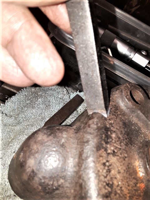
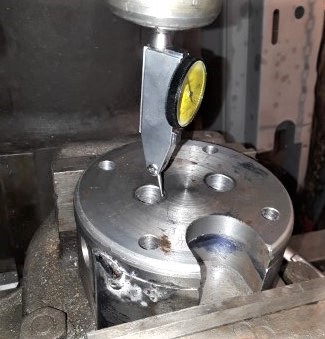
Pic of lathe front spindle bearing cap shows one original shim. Once I am confident in the spindle swap, will find an 8" 4 jaw chuck and get back to that head top cover radius task. BTW, I dont have a radius tool and would like to make one by hand, and my bench grinder doesnt have the right stone apparently so thats another "make the machine to make the part" aspect!
The only uncertainty I have with this is whether I will have made enough water jacket area to keep the head cool. Trying to leave no less than .250" wall thickness anyplace and with the passages, valve pockets, spark plug pocket etc it's kind of "precision guesswork". I did buy enough 5" diameter cold rolled 1018 to make at least one more if something goes horribly wrong. If not, hopefully this will be a roadmap for other YT owners to bring the machine back alive since cylinder head corrosion seems to kill these more than anything as far as I can tell.
 |
narrabay2
Member
Username: narrabay2
Post Number: 19
Registered: 10-2019
| | Posted on Monday, January 06, 2020 - 10:01 pm: |
|
Hey I just thought of an idea... fill the good original cyl head I have with water/coolant then drain it into measuring cup. I can use a water sight glass since it is bolted to the engine now. then try to get the new one to hold as much water as possible, hopefully a good percentage of the original. this should (???) approximate the surface area the water gets to cool. or at least give a comparison... |
ned_l
Senior Member
Username: ned_l
Post Number: 205
Registered: 08-2012
| | Posted on Friday, January 10, 2020 - 03:21 pm: |
|
Glad to see you are still at it; and as Ernie said, it is admirable the lengths you are going to!
I like your idea about measuring and comparing the QTY of coolant, that sounds like a good comparison |
narrabay2
Member
Username: narrabay2
Post Number: 20
Registered: 10-2019
| | Posted on Tuesday, January 14, 2020 - 10:26 pm: |
|
Thanks ned, that was actually Miro, the man who got me going on the Dispro, which led to a big bill at the machinist, which led to my completing machinist school, which led to almost all my disposable income for a couple years putting together a machine shop! LOL!
The YT head progress somewhat slowly continues... I was able to install the new large spindle into the lathe. More learning, and that was great. Learned about shimming the headstock bearing caps for .001" clearance, etc. So finally tonight got back to establishing the radius on the cylinder head top. I made a HSS tool on the bench grinder, and chucked the part, indicated it to about .002" put the lathe in back gear, and it all worked out really well!
Pics:
 |
narrabay2
Member
Username: narrabay2
Post Number: 21
Registered: 10-2019
| | Posted on Tuesday, January 14, 2020 - 10:26 pm: |
|
 |
narrabay2
Member
Username: narrabay2
Post Number: 23
Registered: 10-2019
| | Posted on Sunday, January 19, 2020 - 01:01 am: |
|
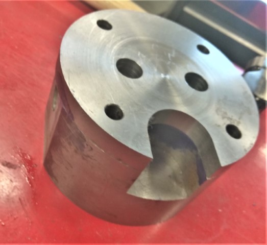
Getting deeper in all the time with water jacket areas... no disasters yet!
 |
ned_l
Senior Member
Username: ned_l
Post Number: 208
Registered: 08-2012
| | Posted on Monday, January 27, 2020 - 09:30 pm: |
|
Looking real nice! |
narrabay2
Member
Username: narrabay2
Post Number: 27
Registered: 10-2019
| | Posted on Monday, February 10, 2020 - 06:13 pm: |
|
Thanks ned. I should mention that the irregular "contours" on the floor of the water jacket and some of the sides is intended to produce more surface area for cooling. at least that is my thinking and why I left the ball end mill in the machine to nibble away at the water jacket pockets.
Getting close to making the valve guides. They will be a press-fit using loctite to seal them to both the cylinder head itself and the top cover which is a half inch thick.
once they are installed then I will have my local machine shop cut the valve seats concentric to the valve guide holes and to the valves that I have in hand.
does anyone here have a recommendation as to what material to make the valve guides out of? I am wondering if regular steel such as the 1018 the head is made out of, stainless steel, or some kind of oil or graphite impregnated material would be better? |
narrabay2
Member
Username: narrabay2
Post Number: 28
Registered: 10-2019
| | Posted on Saturday, February 15, 2020 - 09:59 pm: |
|
OK did my own research, and you shouldnt make a valve guide from steel as it can gall. They are best made from cast iron or bronze etc. There was a change of design anyway due to the 5/8" top cover valve holes not in perfect alignment with the ones in the heads. So new (probably better) plan is to weld 11/16" diameter steel guides into the head itself, welding on the top, and then re-drill the top cover holes correctly located this time, and drop the cover on and weld them where they stick through. THEN, drill and ream the 11/16" steel guides for the bronze guide inserts.
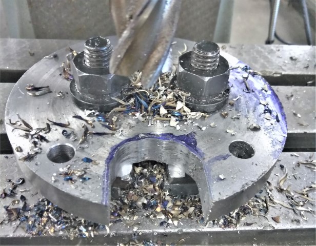
I took down the top of the guide mounds .130" to accomodate the weld.
Similar plan for the bolt holes except those bushings will be interference fit with locktite.
The water jacket itself is pretty roomy now and I am somewhat comfortable.
The YT seems to have the water enter the side of the cylinder water jacket and comes up through 3/8" holes into the head, exiting at the exhaust. I wonder why. Wouldnt it make more sense to have the cooling water enter above the exhaust and then down to the cylinder and out the side? That way temps would be more uniform. I suspect that Palmer wanted the water to come out right where it enters the exhaust and there may even have been direct entry to the exhaust manifold for a clean look.
Anyway neither here nor there on that. The water holes are drilled and now the head is ready to accept cooling water into the bottom of this head. It will be easy to drill and tap for a pipe fitting just above the exhaust port area in the cyl head top cover which is .500" thick.
The water jacket looks messy but to my thinking that just creates more surface area and maybe turbulence for better cooling.
Also chucked the top cover and chamferred the bottom edge to accomodate the weld bead a little better.
 |
ernie
Senior Member
Username: ernie
Post Number: 2564
Registered: 01-2002
| | Posted on Monday, February 17, 2020 - 01:04 pm: |
|
Chris,
Your rough cutting to make more surface area isn't a good idea. All that roughness will create turbulence in the water jacket. If you look at the inside of a water jacket the surfaces are pretty smooth, other than the grain of the metal it was cast from. The reason for smoothness is something called laminar flow. You want the water to be as much as possible 100% flowing in contact with the walls of the water jacket. This allows the best temperature exchange between the walls of the water jacket and the coolant.
As to the coolant flow in the water jacket do you suppose the engineer/s at Palmer that designed the engine did the necessary calculations to cool the engine properly even considering which way and how the cooling water flows in the engine?
I suspect they did...
Also hot water doesn't like to go down, even when pumped, it looses a lot of efficiency forcing it to flow down.
Now all this being said the water pump on a YT1 is plenty big to cool the engine. Running raw water cooled they ran cold except for right by the spark plug on the aft face of the head. That area didn't have any water jacket intentionally to keep the plug hot. Once you get your freshwater cooling system done you will be amazed on how little water flow the engine needs to be kept at 180 deg F or so.
This being the case stop worrying about all of the above and put the thing together and run it.
Just trying to save you some grief down the road
Ernie |
narrabay2
Member
Username: narrabay2
Post Number: 29
Registered: 10-2019
| | Posted on Wednesday, February 19, 2020 - 08:38 pm: |
|
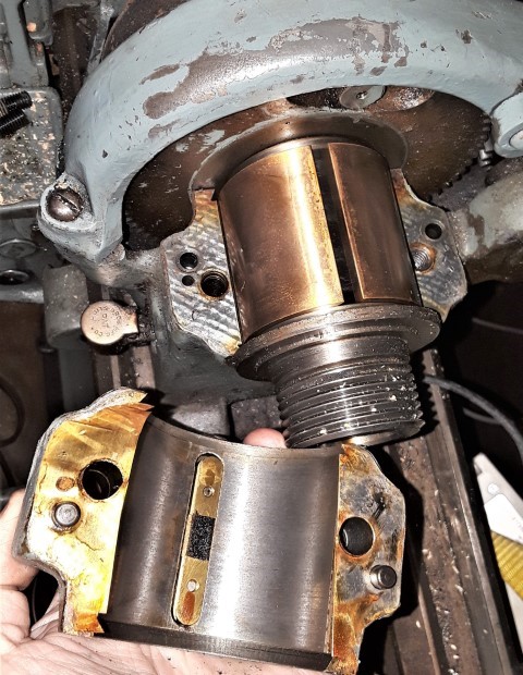
Thank you Ernie as always. I plan to exit the water above the exhaust passage as original. The original did have a water inlet below the exhaust passage that I cant replicate. But I think it should be okay with just the two 3/8" holes either side of the intake runner, flowing across the jacket and out the exhaust area. I suppose if it gets too hot (not likely as you said), it would show on the paint.
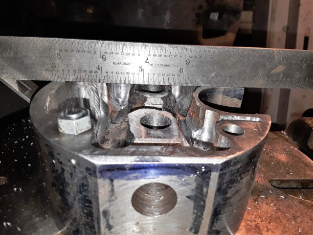
Anyway, I made a rookie mistake. The top cover holes are not located identical to the head body. Not sure how that happened. My machinist instructor would probably punch me in the face for that! (not too hard though as we're friends)
No matter, I tack welded the cover on and will true up the valve guide holes in the top to the ones in the body. The cover holes will be a bit larger diameter but I'll just turn the valve guides larger there. The guides will be welded in where they stick through the water jacket, then the top cover welded on, then welded around the valve guides where they stick out the top cover. Then drilled for the bronze guide liners, then the valves turned to diameter, then the valve seats cut to the valves which I may have my local engine machine shop handle.
Also will true up the top cover bolt holes since I have to enlarge them anyway and run that larger diameter into the head a bit for the press-in bushings to seal the water from the head bolt holes.
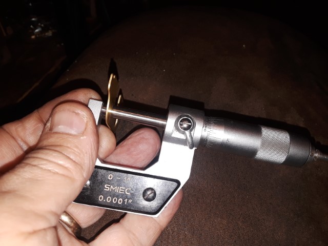
My dial test indicator probe not long enough so I have one on order with longer probes. See pic.
It's been almost 24 months on this but if I had to press, I could do another one in days or a week. When my BP has CNC added, shorter than that. Hopefully this works well, and is a solution for any YT1's with everything good but the head rotted out!
 |
narrabay2
Senior Member
Username: narrabay2
Post Number: 117
Registered: 10-2019
| | Posted on Friday, July 24, 2020 - 11:26 pm: |
|
Just to give a little update, I ordered a 7/8 and 1" end mill for drilling the valve guide bushings. The above picture I think it is backwards. Need to indicate the valve side and then drill through from the combustion chamber side. Then I can cut the spot welds and remove the top cover, press in the VG bushings, get those tig welded in place, press the top cover on them, get them tig welded again. Drill and press bushings into the head bolt holes with loctite and weld the seam all the way around. The head will then be sealed.
Be nice if this all works and this topic can be a road map for other YT owners who lack a cyl head.
We'll see! |
ernie
Senior Member
Username: ernie
Post Number: 2602
Registered: 01-2002
| | Posted on Saturday, July 25, 2020 - 08:43 am: |
|
Why all the welding?
The original valve guides were just pressed in. In fact most industrial engines have the valve guides pressed in. When repairing a cylinder head with cast in valve guides the cast in ones are machined out and the new replacement guides are pressed in. With the right interference they won't move.
I just did a quick Google search and found .001 to .0015 interference for cast iron. When I worked in an automotive machine shop back in the 70s if we were worried about them moving we just put some JB Weld on them.
Why bushings on the head bolt holes?
As to the head cover the valve guides will line it up since it appears you are going to indicate everything in from them. Just use a good RTV on the head cover making sure you have a good thin bead around everything. Bolt the head on the cylinder and let it cure.
This way you don't have the heat of welding and you can remove the cover in the future if needed to clean out the water jacket.
I made some Palmer PW 27 heads years ago by slicing a bad salt water head apart horizontally, then fixing the upper and lower halves with bondo, modeling clay and what ever I had to get it shaped right. Then had the 2 parts cast. Then a little surface machining, drill the head bolt and water jacket holes and tap the spark plug threads. RTV on the 2 halves and bolt it on the engine. Wa-la a good head.
Hope this helps
Ernie |
narrabay2
Senior Member
Username: narrabay2
Post Number: 118
Registered: 10-2019
| | Posted on Saturday, July 25, 2020 - 10:52 am: |
|
hi ernie, yup, there are several approaches that can work. very cool how you made those heads. I wonder if that method could work for a YT head.
But anyway, to answer your questions. The cast iron valve guides will be pressed in. Its the ~1" diameter bushings that will be welded as part of the head which will seal them and make it one unit. I dont anticipate ever wanting to open this up and welding is water tight. (I know rtv is too). Just another way to do it.
There is also the issue of the "side car" intake passage feature. That has to be attached somehow and welding it on will be quick strong and tite. And that would tie the top and bottom together anyway
As to the head bolt holes, there is a seam between the upper and lower halfs inside the 4 head bolt holes. I plan to drill them oversize just down into the lower half a bit and press in little sleeves with loctite just to seal those little seams in there.
So I appreciate very much the idea. There are several ways to approach this, separate halfs, one unit, casting, etc, and I can only try/learn and do one. (at a time!)
I have a broken YT head someone here sent me, maybe someday the casting upper and lower idea that you did would be a fun experiment too. We went kayaking with friends a couple weeks ago and our friends new husband told me about a foundry here in RI. In fact he said there was more than one. His friend restores old cars and casts needed parts at the foundry then machines them.
BTW did you machine your castings yourself and do you have any pics of making those by chance? Was the foundry around here? Is that expensive? |
ernie
Senior Member
Username: ernie
Post Number: 2604
Registered: 01-2002
| | Posted on Saturday, July 25, 2020 - 01:57 pm: |
|
Oh yea I forgot about the intake side car. Yup I guess the top should be welded so all the parts are one piece.
Yes I machined the PW heads I had cast. The foundry was local over here in SE Mass but it has been gone for years. I think they charged me 50 bucks for each 2 castings. I think that was a minimum charge. I may still have one of the heads around here somewhere. If I do I will post some pics. |
ned_l
Senior Member
Username: ned_l
Post Number: 219
Registered: 08-2012
| | Posted on Monday, August 03, 2020 - 11:12 pm: |
|
Great progress! |
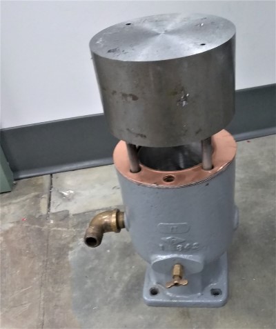
narrabay2
Senior Member
Username: narrabay2
Post Number: 270
Registered: 10-2019
| | Posted on Friday, February 07, 2025 - 02:09 pm: |
|
I did not finish this (yet)n because I found a NOS "aftermarket" YT head (believe it or not). It's a little different on the outside but definitaely a YT head in all the right ways. |