|
| Bemus Distributor- 1902 Thrall 2-cycl... |
| Author |
Message |
    
Mike Adams
| | Posted on Monday, April 15, 2002 - 01:52 pm: | 


|
Andrew,
In one of my previous question sessions, I asked about the top of the Bemus Cap. It has a threaded stud in the center which holds a spring and a 3/8 ball in place. I can't see where this ball makes contact with anything, so I have to ask, what is it for, and what wire hooks to it? If this is the coil wire connection then there has to be some kind of metallic connection between the offset pin inside the distributor and the spring loaded 3/8 ball. Hope someone has an answer. Also, I took Ernie's advice and sent the engine to Bill Wolf in Maine. Thanks, Mike Adams |
andrew
| | Posted on Monday, April 15, 2002 - 05:41 pm: |
|
Mike,
Did you get the Old Marine Engines book by Stan Grayson and the Palmer Handbook that I sent to Quinten? There is a brief section that includes the Bemus timer in the Old Marine Engines book on page 58.
I believe that the vertical rotating shaft (or spool) on the inside only has one contact point, with the remainder of the circumfrence non-conductive. The contact is made with a threaded stud from the side, one for a single cylinder and two for a two cylinder. Ignition wires to the "interupt" on the buzz coils are attached to those studs. As I remeber your timer has one threaded hole for a stud, and needs to have another one located 180 degrees opposite. You will need two buzz coils for a two cylinder engine. There are some wiring diagrams in the Palmer Handbook.
Regards,
Andrew |
Mike Adams
| | Posted on Tuesday, April 16, 2002 - 04:20 pm: |
|
Andrew, Yes, we have discussed that before, but the threaded stud I am talking about now is in the center of the top brass cap( the cap with the Bemis name on it) and on the underside of the cap is a spring loaded 3/8 steel ball, also in the center, that does not make contact with anything inside of the Bemis timer. Mike |
andrew
| | Posted on Monday, April 22, 2002 - 05:37 pm: |
|
Mike,
Dick Day has sent in the following picture and information.
Quote:Mike Adams with a 2 cylinder Thrall asked a number of questions. Number 5 concerned the Rotor of the Bemus timer. His was apparently missing and he didn't know what the top cap ball was supposed to connect to inside the timer. I have attached a Bemus Timer drawing that quite clearly shows the rotor and how its upper and lower surface are relieved to permit the ball in the cap to track the rotor as it rotates. I should add the rotor is beveled on both upper and lower face so when one side becomes worn you can turn the rotor over. Regards Dick.
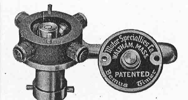
The timer in the photo shown is for a four cylinder engine (I guess it could actually be used for a 1, 2, or 4 cylinder engine).
Regards,
Andrew |
Mike Adams
| | Posted on Tuesday, April 23, 2002 - 11:09 am: |
|
Dick and Andrew,
I appreciate all of this input and sometimes answers lead to more questions and I apologize for that,but please realize that my short marine engine career has been focused on 6 & 8 cylinder inboards like Hercules,Ford,G.M., etc., and I have never seen a Thrall engine, let alone a Bemus Timer, before last summer. So with that in mind, my questions are as follows; 1. When you say relieved, do you mean the top and bottom surfaces of the rotor are machined with a concave surface to accept the radius of the ball in the cap? 2. What are the dimensions of the rotor ( length,width, depth of relief, etc.), and what is it made of? 3. As asked in my first note of April 15, 2002 to Andrew, what wire fastens to the center threaded stud of the Bemus cap? 4. I have looked through the Palmer book and in the Old Marine Engine book on Page 58, it shows a Bemus Timer, and it talks about a "spool composed of a fiber insulation material except for a brass segment that came in contact with a terminal mounted on the case." Is this "spool", the rotor you are talking about? 5. The center core, that is the part with the offset 1/4 inch dowel sticking out of the top,on my Bemus timer is made of steel. Is that correct? Bye for now, Mike Adams |
rbprice
| | Posted on Tuesday, April 23, 2002 - 07:53 pm: |
|
Mike -
The "fiber insulation material" is most likely a piece of linen (or possibly, paper) based phenolic laminate widely used as an insulator in all kinds of electrical devices. It is readily available in small pieces from McMaster-Carr supply http:\www.mcmaster.com
Also, any machine shop could make a part if you can give them a dimensioned dwg. or an old part. The brass insert can be held in place with super glue or epoxy or just pressed into a properly sized hole.
Hope this is of some help.
Bob Price |
Richard Day
| | Posted on Tuesday, April 23, 2002 - 08:34 pm: |
|
I have BEMUS timer but havn't been able to locate it yet will ASAP. I will give you a set of dimensions. The rotor is steel as I remember it and I dont think it is radiused to pecisely track with the ball in the cap. The cap center wire goes to the battery negative. The contacts on the outside go to the timer contact on each coil. One coil for each cylinder. The positive battery connection goes to the bottom contact on each T-Ford Buzz coil. The spark lead from each coil goes to the cylinder. Put an on/off switch in the positive battery lead to the coil or coils if you have a mutiple cylinder engine. |
Mike Adams
| | Posted on Monday, May 20, 2002 - 08:15 am: |
|
Robert, Richard, Andrew, or anyone else who would like to jump in.
I am stalled on this Bemus Timer problem. No one seems to know for sure what the "rotor" looks like and what it is made of. If someone does know this information, please post it here or send me the information and a sketch by snail mail to;
Mike Adams
483 Burritt Road
Hilton, N.Y. 14468
Thanks,
Mike |
Richard Day
| | Posted on Monday, May 20, 2002 - 08:15 pm: |
|
Mike the rotor is steel and it slips over the stud on the top of the shaft in the center. The stud is offset from the center of the shaft so as the shaft turns the rotor travels in a circular motion completing the electrical circuit from the top cap to each of the the contacts around the insulated ring. As the rotor rotates around the shaft it also rotates on the stud it sits on. This make for a rolling connection to each side contact. The rotor can be turned over when contact surfaces wear and this will expose a new unworn area. I cannot find my Bemus timer so I cannot give you precise dimensions. Its about 3/4" thick. 3/4" in diameter. Easy enough to make. |
Mike Adams
| | Posted on Tuesday, May 21, 2002 - 01:35 pm: |
|
Richard,
Thank you, but I would still like to get a drawing with dimensions, if I can. There is no sense trying to make this part if I have to remake it again and again because my last guess was wrong.
So, if anyone has the specs on this Bemus Timer rotor, please post it here, or send the information to;
Mike Adams
483 Burritt Rd.
Hilton, N.Y. 14468
Thanks again,
Mike |
bob
| | Posted on Tuesday, July 30, 2002 - 02:07 pm: |
|
I found a bemus timer last weekend at the brooks show,seems to be fairly complete does anyone know how the wire attaches to the timer contact or what type of connector was used in that era... thanks bob........... |
Mike Adams
| | Posted on Saturday, August 17, 2002 - 01:16 pm: |
|
Bob,
I would like to talk to you about the Bemus Timer. Please email me at [email protected]
Mike Adams
483 Burritt Road
Hilton, N.Y. 14468
(585)392-9627 |
|
|
|


|