| Author |
Message |
    
Ernie
Senior Member
Username: ernie
Post Number: 678
Registered: 01-2002
| | Posted on Tuesday, June 19, 2007 - 01:53 pm: | 


|
This just came in and looks like some really good basic information on marine exhaust systems for smaller engines like the palmer P-60 and others of similar size.
With comments on using wrought copper by Dick Day.
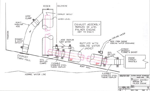
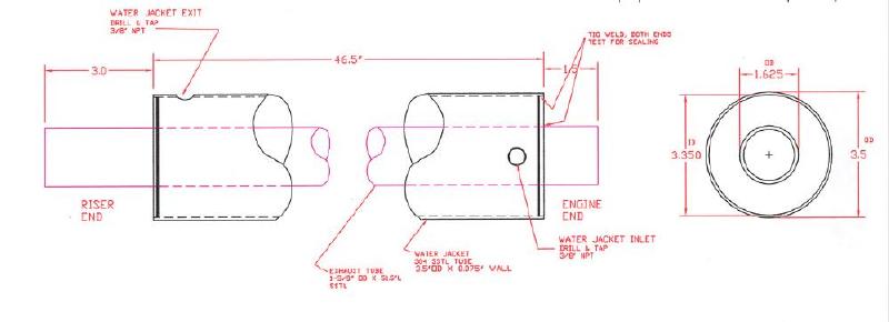
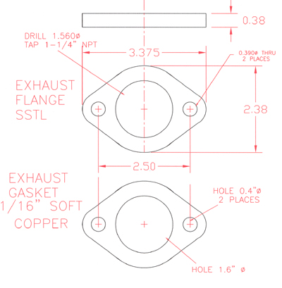
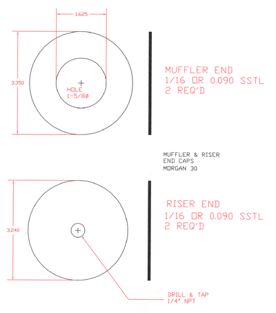
Subject: Suggested Exhaust System for Palmer P-60 in the Morgan 30. This system would be suitable for other comparable marine engine installations.
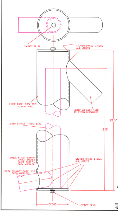
Drawing no. 1 of 5. This drawing lays it out systemically in such a simple matter that anyone can use it to adapt Howard’s approach to fit any hull or engine just using a little common sense. The water level note and the way the exhaust is discharged from the riser keeps the likely hood of cooling water being drawn back into the engine during engine shut down is very important
Howard’s design in stainless steel is great. A lot of working watermen are probably more comfortable working with copper pipe and wrought copper pipe fittings. Cast brass pipe fitting for this sort of application are really not suitable structurally. Wrought copper fittings are widely available from plumbing supply houses in sizes that are comparable to Howard’s dimensions. Wrought copper and copper pipe braze very well with so called PHOS COPPER brazing rod and they will easily stand up to salt water and heat. For example to make the muffler simply take a piece of copper pipe the length of the muffler wanted add wrought copper end caps with holes cut in their ends to permit the inner pipe to pass through end to end and simply braze the joints. One can do the same general approach for the riser using wrought copper fittings coming into the bottom of the riser with 90 degree radius bends. Where a 90 degree joint between the muffler and the riser is possible the section of flexible tubing could be eliminated simply joining the water cooled muffler to the riser. For operation in cold climates or for system drainage provision should be made to drain the muffler from the bottom of the muffler and riser section.
For anyone desiring additional information these drawings were provided by Howard E. Taylor, President Custom Applied Technology Corp.2361 Whitfield Park Ave
Sarasota , Florida 34243 Ph: 941-751-5656 Fax: 941-758-0815 E-Mail: [email protected] Website: www.catec.com
Howard has also documented the rudder, c'board, and c'board control cable designs for the Morgan 24 & Morgan 30, these are available on AutoCAD. If anyone wants them contact Howard at the above e-mail address
 |
carlos perez
Member
Username: melekai
Post Number: 16
Registered: 03-2012
| | Posted on Monday, May 07, 2012 - 11:14 pm: |
|
ernie, please email this diagram to me , i need to replace my palmer 60 exhaust, this is very useful for me. also I'm looking for a thermostat for my palmer60 salt water. thank you for the info |
Marc Lohrisch
New member
Username: lohrisch
Post Number: 1
Registered: 04-2012
| | Posted on Tuesday, May 08, 2012 - 10:19 am: |
|
My P-60 (in an Islander 30) has a very different configuration. It uses a standpipe muffler with water into the top from the engine, hot exhaust into the bottom direct from the manifold (no cooling water - just hot, wrapped in asbestos, which I'm replacing), then cold exhaust out the side to the transom. Had me completely stumped as a could not find a muffler with 3 "holes" in it. Finally, through this forum, found out that it is a standpipe and found one at Moyer Marine. |
Matthew Lennarz
Member
Username: mlennarz
Post Number: 26
Registered: 06-2010

| | Posted on Tuesday, May 08, 2012 - 11:44 am: |
|
Hi,
I am trying to learn about my P60 Exhaust System more... I am curious if anyone knows whether or not the exhaust pipe in any of these systems is straight-thru, or has some type of baffling or other restriction. My system seems to have something (not sure whether or not it is intended to be there) partially restricting the exhaust pipe a foot or so after it leaves the exhaust manifold. Mine does not use a standpipe, but uses two water jackets along the hot exhaust pipe, then a goose neck up and back down before it leaves through the exhaust port in the transom.
Should the exhaust pipe be completely unobstructed from motor to transom? Could the "obstruction" about a foot in be some type of one-way valve that prevents water from back flowing into the motor? Any thoughts would be helpful! Thanks. |
Eddie Ross
Senior Member
Username: eddie
Post Number: 293
Registered: 04-2003
| | Posted on Wednesday, May 09, 2012 - 12:48 pm: |
|
 |
Eddie Ross
Senior Member
Username: eddie
Post Number: 294
Registered: 04-2003
| | Posted on Wednesday, May 09, 2012 - 12:49 pm: |
|
 |
Matthew Lennarz
Member
Username: mlennarz
Post Number: 27
Registered: 06-2010
| | Posted on Wednesday, May 09, 2012 - 02:00 pm: |
|
Thanks Eddie. I've seen these, and it leads me to believe that the exhaust pipe is straight through without any valves or baffles. Mine is a little different, but I am beginning to believe that there is some type of baffling or valve that may be broken, because when I probe the pipe, my probe is blocked a little ways in.
Thanks for the info. |
Matthew Lennarz
Member
Username: mlennarz
Post Number: 29
Registered: 06-2010
| | Posted on Tuesday, June 19, 2012 - 04:49 pm: |
|
Update: I completely removed my exhaust system, and discovered that the copper exhaust pipe apparently melted enough so that the water pressure in the first water jacket actually ballooned the exhaust pipe inward, constricting the flow of exhaust and causing blockage. I would have never thought of this and only by detaching and inspecting discovered this. I don't recall ever having run the motor without a good water flow, so I suspect that this happened slowly over years, and finally melted enough to ballon in so much as to restrict the flow.
So, now I will begin rebuilding the exhaust system with new copper.
Again, thanks for the diagrams.
-Matt |
Eddie Ross
Senior Member
Username: eddie
Post Number: 297
Registered: 04-2003
| | Posted on Wednesday, June 20, 2012 - 09:26 am: |
|
Good news. Thanks for the update. |
Matthew Lennarz
Member
Username: mlennarz
Post Number: 30
Registered: 06-2010
| | Posted on Monday, June 25, 2012 - 11:16 am: |
|
So I am still working to identify a replacement exhaust system for my P60 and wanted to get more opinions. Any thoughts are appreciated!
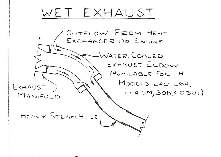
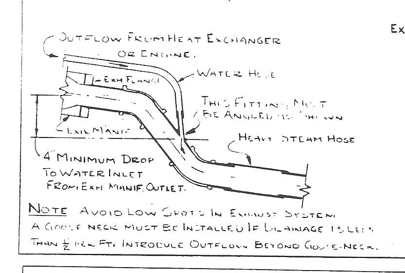
My current exhaust system (which has collapsed), is made up of a 1 1/4 (ID) copper pipe with two sections of water jackets, with the water entering out of the second jacket and into the exahaust pipe just before exit through the transom. While Eddie shared a design for a new exhaust system with water jacket and riser, he also posted two other diagrams (on Wednesday, May 09, 2012 - 12:48 pm), one with a water-cooled exhaust elbow which then flows right into the exhaust pipe, and the second even simplier, with direct water input 4" below the exhaust manifold.
I am trying to understand the pros/cons of each. The water jackets are more complicated to fabricate than I am capable. So I like the simplicity of the water entering the exhaust pipe up closer to the motor, and eliminating the water jackets altogether. However, I am concerned that there is more risk of water accidentally entering the motor. Specifically, what is the risk of this happening? And, when the hot motor is shut off, what prevents steam from the hot system to rise back up the exhaust pipe and into the exhaust manifold causing conditions for rust or other damage? Is that a risk and a reason to go the more complicated water-jacket route?
Thanks for any thoughts,
Matt |
Matthew Lennarz
Advanced Member
Username: mlennarz
Post Number: 31
Registered: 06-2010
| | Posted on Tuesday, June 26, 2012 - 09:15 am: |
|
And, if anyone has an old Exhaust Elbow, like either of those in the diagrams Eddie posted above on Wednesday, May 09, 2012, I am interested in buying it. Please send reply to this post. (I have also posted in the Classified Ads)
Thanks, Matt. |
Chip G
Member
Username: chipg_98
Post Number: 15
Registered: 10-2005
| | Posted on Thursday, July 05, 2012 - 10:47 am: |
|
Here is a photo of my exhaust configuration and a detail of the connection to the muffler using wet exhaust hose and an additional elbow joint that came from the local hardware store.
Hope this helps,
Chip 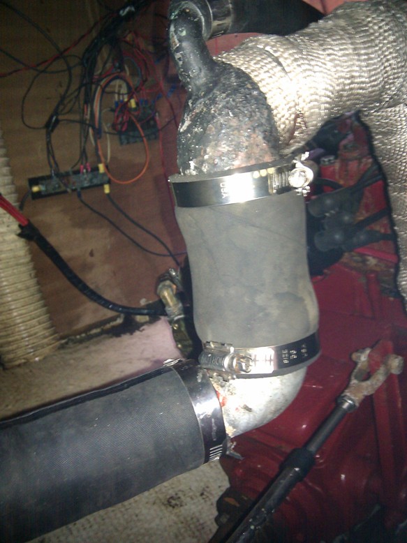 |
Matthew Lennarz
Advanced Member
Username: mlennarz
Post Number: 32
Registered: 06-2010
| | Posted on Thursday, July 05, 2012 - 11:05 am: |
|
Interesting... thanks!
A couple of questions... looks like this is cast iron piping?
And, you say "an additional elbow joint that came from the local hardware store." Are you referring to the last elbow with the smaller water inlet pipe entering through it? If so, are you saying this is a standard part you bought already with this inlet pipe right through it? I've never seen anything like for sale, but if so, that would be a great solution for me. Thanks for sharing.
-Matt |
Chip G
Member
Username: chipg_98
Post Number: 17
Registered: 10-2005
| | Posted on Thursday, July 05, 2012 - 12:46 pm: |
|
Hi Matt,
I was referring to the elbow shown joining the two black rubber hoses in the 2nd picture in my post above. The one at the top with the small water hose coming in has always been on the engine since before I owned it so I don't know if that was original equipment or otherwise. I would imagine that someone with some basic machine shop tools and a welder could easily make something like it though. The one this you need to keep in mind is that the water needs to spray the metal flange high enough to ensure cooling where the rubber hose attaches. My exhaust pipe hist 350F+ before the water hits it and shows around 150F after the water spray. Wet exhaust hoses are rated for around 200F-ish so you definitely need to ensure sufficient cooling or risk recurring failures of the hose. I wound up using a special silicon hose rated for 600F on mine because of this issue. It seems to be working but if I were to reconfigure mine, I would address the issue. I look forward to seeing how you choose to proceed. |
Matthew Lennarz
Advanced Member
Username: mlennarz
Post Number: 33
Registered: 06-2010
| | Posted on Thursday, July 05, 2012 - 01:07 pm: |
|
Ah... got it now... I didn't see your second photo until I scrolled all the way over!
Yes, I agree on making sure the water has enough distance/time to cool the pipe before the hose. I know that those silicone hoses are not cheap! Based on your photos, I went to Home Depot just now and got all the iron pipe fittings to build basically what you have. The only difference is that I am coming further down past the water entry point and then go into another 90 deg elbow to turn horizontally before it attaches to the hose. So hopefully this will allow the water to cool the pipe to 200 deg before the hose.
Looking at yours again, I was wondering if you couldn't have simply used a threaded nipple in place of your silcone hose? If the pipes are differing sizes, you could use a reducer and a nipple.
Thanks again for posting this... it totally changed my design! I will post once I assemble and install it all. Regards, Matt. |
Matthew Lennarz
Advanced Member
Username: mlennarz
Post Number: 35
Registered: 06-2010
| | Posted on Monday, July 09, 2012 - 09:41 am: |
|
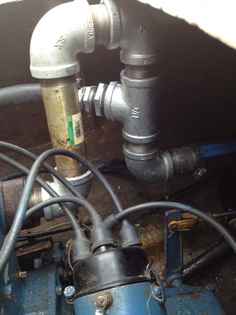
Update on replacing my wet exhaust system on my P-60:
I used Chip G.'s input and found all the galvanized steel pipe fittings at the local HD. All screwed together without need for any modifications. Note that I used a simple 90 degree "Tee" for the water input into the exhaust. Most designs show this as an angled input (less than 90 degrees), but it seems that with the 6" drop from the top of the gooseneck, it should be sufficient to prevent any backwash into the manifold. I used high-temp gasket sealer on all the threads and tighten everything down.
(Not seen in photo): After the galvanized exhaust elbow, it attaches to a Sheilds-brand wet exhaust hose, then to a Centek "Vernalift" waterlift muffler, which then connects to another length of exhaust hose to the transome. The waterlift muffler both cools and quiets, while it protects from backwash or syphoning.
This isn't the most elegant design, and doesn't seem as efficient in cooling at the exhaust elbow versus my old water-jacketed design, but the parts are all readily available and not expensive (vs. having a new exhaust system custom designed and fabricated.)
I will say, through all of this I have learned a lot about marine wet exhaust systems. Thanks again to everyone who posted info... it was all helpful.
-Matt
 |
David V.
Member
Username: cdsailor
Post Number: 4
Registered: 09-2016
| | Posted on Tuesday, September 13, 2016 - 08:32 pm: |
|
Matthew,
Do you still check this board? If so, how has your exhaust system worked? I'm thinking about ditching the 40-year-old original exhaust system in my Morgan 30 for a waterlift system. Curious to know how your system has performed.
Thanks,
David |