| Author |
Message |
    
Ernie
| | Posted on Tuesday, June 08, 2004 - 08:09 am: | 


|
Here are drawings and instructions from J.B. Castagns on how to make a cheap buzz coil that really works good. I saw several at the Calvert Show and they will put out a good 1/2 inch spark.
Buzz Coil
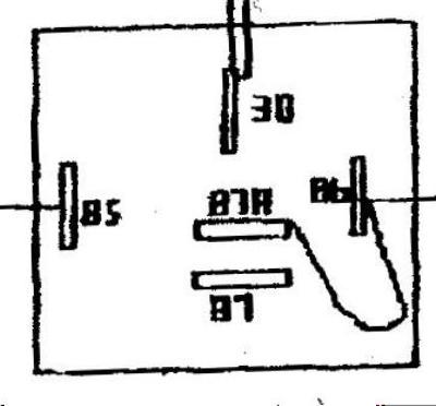
This is a buzz coil made from automotive parts. The coil is preferably an internal resistor type, but an external resistor will work. The relay is a Bosch type, used for accessories on most late model cars. A trip to the junkyard should get you a handfull for $5.00. Look for the ones with 5 terminals, some only use 4 and won't work. Note make sure that there are terminals 87 and 87a. If the relay has 2 terminals numbered 87 this won't work. I use Ford condensors because the brackets work well, but any auto condensor should work. The relays usually have a schematic on the cover. You will see that terminals 85 and 86 are the coil in the relay. These are wired in parallel with the automotive coil, one wire from the neg. terminal of the coil to 85 and one form the positive to 86. Terminal 30 is the common on the points of the relay and 87a is the normally closed. A wire is jumped terminal 86 to 87a. A wire is connected from terminal 30 to the battery positive. The condensor can be screwed onto the coil terminal, this mounts it and makes a connection, a wire is then run run to terminal 30. If you look at the diagram you will see that this is giving you a condensor across the relay points. The second condensor is optional, but you should be used if your engine has points in the timer. If the points don't open fast and clean this system will continue to draw an arc across the points, possibly causing a misfire. Condensor 2 is wired to work with the points in the timer. The relay acts as a buzzer in this system. When power is supplied to the coil the relay coil is energised also. This causes the points to open in the relay, de-energising th ecoils and firing, th epoints close and repeat.
J.B. Castagnos
[email protected]
 |
Ernie
| | Posted on Tuesday, June 08, 2004 - 11:38 am: |
|
Andrew,
Can you add this to the "tech" section?
Thanks
Ernie |
Richard Day
| | Posted on Wednesday, June 09, 2004 - 08:07 am: |
|
Why not add a second coil and it uses the buzzer as a "Master Vibrator" Model T Ford style? Add a third coil for a three cylinder engine and a fourth for a four cylinder. |
J.B. Castagnos
| | Posted on Wednesday, June 09, 2004 - 01:29 pm: |
|
Dick, the buzzer may be able to handle more than one coil but they're hooked in parallel with the coil, all coils would fire at once. This would work for an opposed engine where both fire at the same time but not one firing 180 degrees apart. |
Richard Day
| | Posted on Wednesday, June 09, 2004 - 09:29 pm: |
|
What I had in mind is the multiple coils would only be grounded one at a time so the buzzer circuit would only see one coil at a time. Thats the way the master vibrator circuit works. Will have to work on a diagram as soon as I can get my hands on one of the buzzers. How is John doing by the way. Regards to you all. |
Paul Leboeuf
| | Posted on Thursday, June 10, 2004 - 07:56 pm: |
|
I can vouch for JB Castagnos' buzz coil. Its so easy to put together and will def. knock your socks off if by chance you hold on to the spark plug wire. oops |
Ernie
Senior Member
Username: ernie
Post Number: 1841
Registered: 01-2002
| | Posted on Tuesday, June 17, 2014 - 08:18 am: |
|
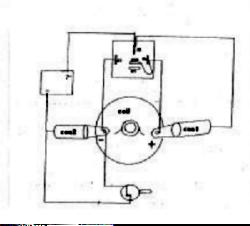
I have been thinking about this on and off for years and finally got around to drawing a schematic.
From what I can find on the net the here is a version of JB's ignition to replicate the Master Vibrator system. Yes the vibrator part vibrated all the time the ignition was turned on. For simplicity I left out the condensor for each coil. It would go from the minus terminal of each coil to ground. The system will work fine without the 3 extra condensors however they will improve timer contact life.
 |
mike zander
New member
Username: ihatethiscrap
Post Number: 1
Registered: 01-2015
| | Posted on Tuesday, January 13, 2015 - 07:17 pm: |
|
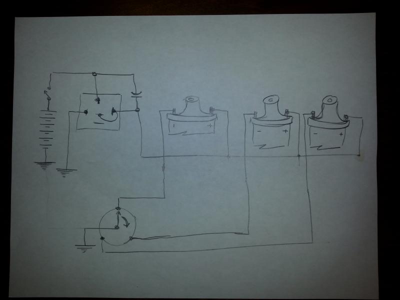
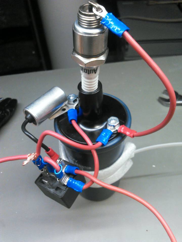
This did not work for me. Here is my setup. What went wrong? I touched the open ended wires to my battery's terminals and nothing happened.
 |
J.B. Castagnos
Senior Member
Username: jb_castagnos
Post Number: 987
Registered: 07-2002

| | Posted on Tuesday, January 13, 2015 - 10:24 pm: |
|
Be sure your relay has terminal 87 & 87a on it, some have tow 87 terminals, won't work. |
mike zander
New member
Username: ihatethiscrap
Post Number: 2
Registered: 01-2015
| | Posted on Tuesday, January 13, 2015 - 10:28 pm: |
|
Thank you J.B. I took care to get the 5 point relay with normally closed on 87a. The exposed pin is the 87, as it is not used in the diagram. I tried to follow the diagram in the OP (as well as I could see that tiny lower picture, anyway).
If I plug the loose ends into a battery, should I not see on the plug? I see sparks at the battery terminal when contact is made, but not on the plug.
Thanks} |
J.B. Castagnos
Senior Member
Username: jb_castagnos
Post Number: 988
Registered: 07-2002
| | Posted on Wednesday, January 14, 2015 - 08:22 am: |
|
Is the relay buzzing? |
Ernie
Senior Member
Username: ernie
Post Number: 1951
Registered: 01-2002
| | Posted on Wednesday, January 14, 2015 - 09:19 am: |
|
Here are the instructions without a picture
Battery plus to relay terminal 30
Battery minus to the timer body
Relay terminals 87a and 86 jumped
Relay terminal 87 not used
Connect coil plus to relay terminal 86
Connect coil minus to relay terminal 85 and the insulated terminal of the timer
Connect the condenser between coil plus and relay terminal 30
Condenser 2 is only needed to protect the timer contacts. The circuit will work without it.
When testing on a bench connect the body of the spark plug to battery minus.
On an engine this isn't necessary because most engines have the timer body grounded or connected to the engine block.
When connected to an engine battery minus will go to the engine block. Some timers have a battery negative connection so the engine can be shut off or reversed from the timer without an additional switch. |
Ernie
Senior Member
Username: ernie
Post Number: 1952
Registered: 01-2002
| | Posted on Wednesday, January 14, 2015 - 09:54 am: |
|
Try to find an older relay without a diode or resistor across terminals 85 and 86. Depending on how the relay that you have was intended to be used the resistor/diode can sometimes create problems when using the relay for a buzz coil
Newer relays have this to prevent the relay from damaging a module when the module turns the relay off.
It is also possible to open up the relay and snip out the resistor or diode.
This relay has a resistor. The little component with multicolored stripes. If it were a diode it would most likely be black with a light colored stripe on one end. Either way just remove it. Do this carefully so you don't damage the wires to the relay coil which are also soldered to the same terminals as the resistor/diode.
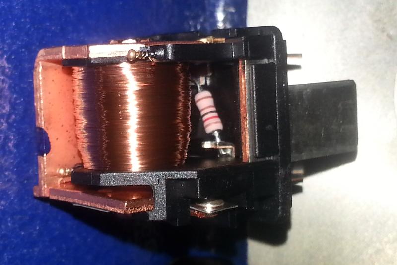
Note this relay is a high current heater relay from a new Mazda. These relays are all similar inside but may be slightly different depending who made it and the actual amperage rating of the relay.
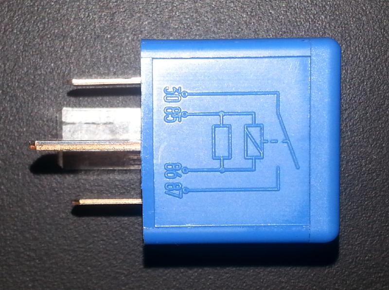
You can tell if the relay has a resistor/diode by looking at the relay schematic on the outside of it. In the pic below the rectangle with the diagonal line is the relay coil. The rectangle in parallel with it is the resistor.
 |
mike zander
New member
Username: ihatethiscrap
Post Number: 3
Registered: 01-2015
| | Posted on Thursday, January 15, 2015 - 12:50 am: |
|
Thanks Ernie. It turns out I had the wiring correct but I had the wrong kind of relay. It has 87 and 87a but they both switch on and off together. I didn't know they made such a thing as a 4 pin relay disguised as a 5 pin relay!
Have a great day. |
J.B. Castagnos
Senior Member
Username: jb_castagnos
Post Number: 989
Registered: 07-2002
| | Posted on Thursday, January 15, 2015 - 07:48 am: |
|
You need a normally open-normally closed relay, the one you had was a double contact normally open, the ones I've seen like this had two 87 terminals, no 87a. The best way to check is to look at the diagram on the relay. |
Ernie
Senior Member
Username: ernie
Post Number: 1953
Registered: 01-2002
| | Posted on Thursday, January 15, 2015 - 08:24 am: |
|
I used the pics above because they clearly show the resistor/diode.
Yes the relay in the pic is a 4 terminal normally open relay and this one won't work for a buzz coil
Ford used a lot of these relays with 5 terminals but 2 of which were numbered 87 for fog lights.
Most of them have an 87 which is normally open and an 87a which is normally closed.
Be careful harvesting this style of relay from European cars at a junk yard. Some of them have the same function but the terminals are located and numbered differently.
Just get in the habit of looking at the diagram on the relay that you are using |
miro forest
Senior Member
Username: miro
Post Number: 787
Registered: 11-2001

| | Posted on Saturday, January 17, 2015 - 12:44 pm: |
|
I have found that if you put a 3 or 4 ohm resistor in series with one of the primary
terminals of the ignition coil,
that it makes almost the same spark across the gap but significantly reduces
the primary current.
I've had it running well with as little as 0.3 Amp in the primary circuit.
I've even put a variable resistor ( 0 -16 ohms) on one of my coils
to see how low i could go, and still get a decent spark.
I've also found that a mylar film capacitor with a 600 V rating , of 0.1 MFD works
just as well as the tubular capacitor, but is far less expensive ( $1 vs $9 or $10).
miro |