| Author |
Message |
    
narrabay
Senior Member
Username: narrabay
Post Number: 81
Registered: 02-2016
| | Posted on Thursday, April 21, 2016 - 09:01 pm: | 


|
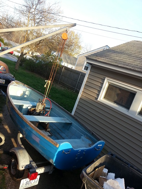
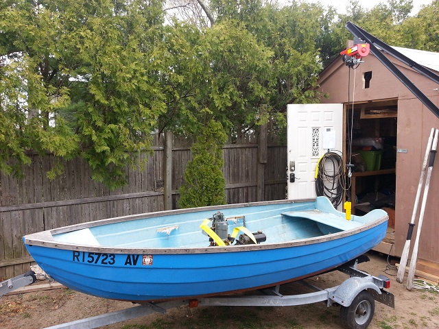
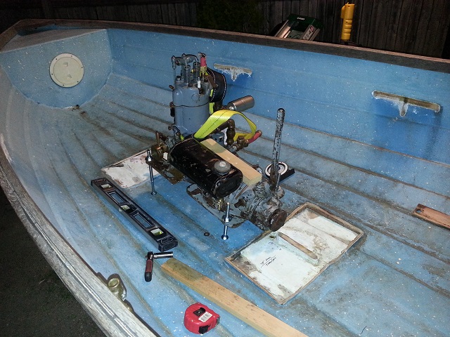
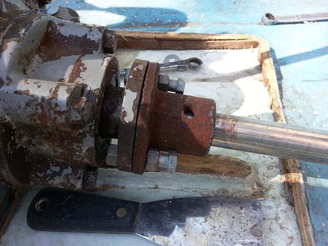
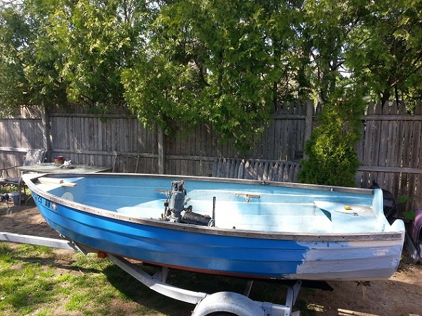
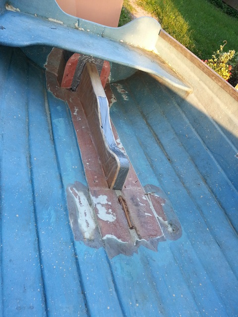
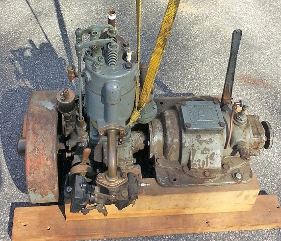
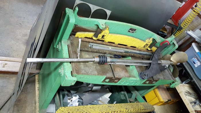
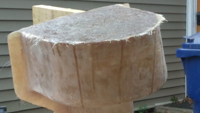
well, finished the "crane" hoist today and had to remove some structure under a seat. but needed to see if this boat really is too small for a YT. One thing for sure, I do NOT like the look of a 15 degree engine. much prefer level, but need a U-joint for that. Suggestions on u-joint welcome! I'd love to make a Dispro type setup for beaching and trailering but that would call for two u-joints, not sure they could take the thrust and the center shaft would need support.
 |
david_doyle
Senior Member
Username: david_doyle
Post Number: 53
Registered: 03-2013
| | Posted on Friday, April 22, 2016 - 12:52 am: |
|
Get a longer boat.
How much flotation is under the stern seat? I am not an engineer but I would apply the precautionary principal and assume that that set up will turtle in a heartbeat if swamped. |
narrabay
Senior Member
Username: narrabay
Post Number: 82
Registered: 02-2016
| | Posted on Friday, April 22, 2016 - 09:39 am: |
|
will be all set on flotation. also the bulk of that engines weight is down low. that being said, at 205lbs this engine weighs as much as a 50-70hp outboard! |
bruce
Senior Member
Username: bruce
Post Number: 551
Registered: 07-2002
| | Posted on Friday, April 22, 2016 - 10:34 am: |
|
This hull cry's out for a 65 pound 3 hp copper top Arrow or Waterman located behind the mid-seat...The YT will pound the bottom loose with out added engine stringers and bottom frames |
david_doyle
Senior Member
Username: david_doyle
Post Number: 54
Registered: 03-2013
| | Posted on Friday, April 22, 2016 - 11:51 am: |
|
Please post when you get it in the water. Will be interested to hear about it. |
scott_n
Senior Member
Username: scott_n
Post Number: 272
Registered: 02-2008
| | Posted on Friday, April 22, 2016 - 01:26 pm: |
|
looks like you will need stringers and shaft log |
narrabay
Senior Member
Username: narrabay
Post Number: 83
Registered: 02-2016
| | Posted on Friday, April 22, 2016 - 01:32 pm: |
|
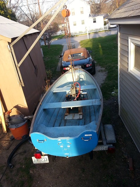
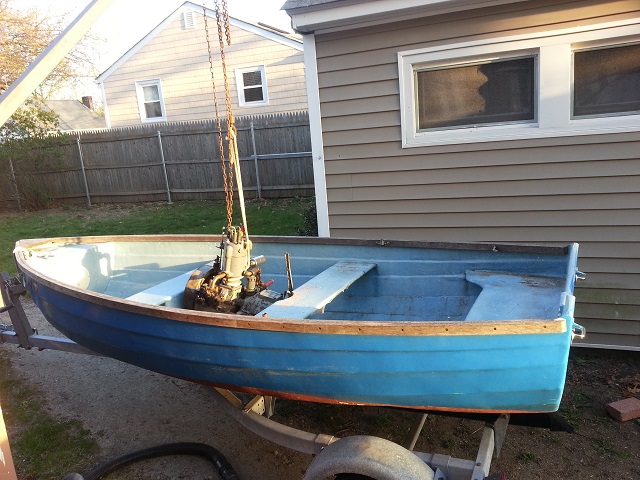
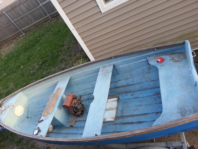
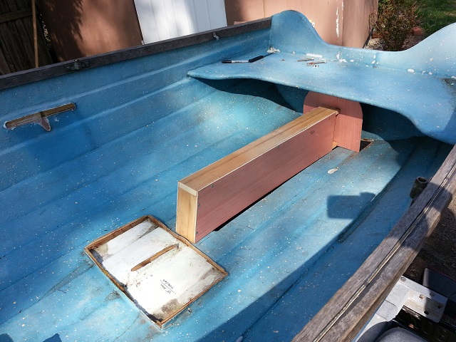
OK I started to reply but got sidetracked. As to the hull structure, I should have included my plans for properly glassed stringers and probably a rib or two. This hull is well-made, hand laid fiberglass cloth not some chop-gun junk.
That being said, I really didnt know how the engine would look until I dropped it in. Had to build the crane, and then remove one under-seat box which was surprisingly well made I might add.
Now that it's been dropped in to see, looks just a bit big. Ideally, a 14ft hull with 8-12" more beam would be better.
As to the smaller engine idea, where to find one? I might be up for that. I also have a Kermath Sea Pup available (no reverse gear), but the RPM is a bit high and was planning to use that for display/demonstration rather than in a boat.
Anyone have an old smaller one avail? I could also get an evinrude "row boat motor" and run it as an inboard., and there is a picture of magazine article on that I have somewhere.
This is a fun project and its also fun to discuss here, as long as helpful replies are getting posted of course. |
david_doyle
Senior Member
Username: david_doyle
Post Number: 55
Registered: 03-2013
| | Posted on Friday, April 22, 2016 - 03:50 pm: |
|
An Evinrude row boat motor (outboard)is the EXACT proper motor for that boat just the way Ole designed it. Why destroy an antique to end up with a poorly appointed craft???
Destroying a good hull and a good engine for no real purpose is kind of an aggravating thing to watch. |
narrabay
Senior Member
Username: narrabay
Post Number: 85
Registered: 02-2016
| | Posted on Friday, April 22, 2016 - 05:38 pm: |
|
dave maybe it will make you feel better to know that using a row boat motor powerhead was actually published in a magazine of the 1930's. anyone can clamp an outboard motor onto a boat. in the case of this boat, I did that last summer. it sucked. not much room back there to start, tend the motor and operate. left me all twisted up. bow went up and it pigged along. The hull is narrow astern, and not the right bottom shape to plane (even with 15hp!).
here is the Irreducible which specifically cites using a row boat power head, which may even be found without the lower leg. In fact, if you want to channel your frustration at someone elses project ideas, find me an orphaned row boat motor power head and I'll use that while looking for a bigger hull for the YT.
here is the irreducible
I will add that the only way this hull would work with an outboard is to make a motor well ahead of the rear seat... |
david_doyle
Senior Member
Username: david_doyle
Post Number: 56
Registered: 03-2013
| | Posted on Friday, April 22, 2016 - 06:19 pm: |
|
edit |
ernie
Senior Member
Username: ernie
Post Number: 2264
Registered: 01-2002

| | Posted on Friday, April 22, 2016 - 06:22 pm: |
|
Good point David
1 ruined rowboat motor and 1 ruined boat
Seeing it with the YT sitting in it If I had that boat I have a nice 40 Plus Seagull that would work perfect for the time being until a good rowboat motor showed up.
I suspect the article by Weston Farmer was written when Rowboat motors had no real value and were real common on the "junk" rack at the back of the local outboard shop. I can't find the original right now but I seem to remember he drew that up in the 40s. |
david_doyle
Senior Member
Username: david_doyle
Post Number: 57
Registered: 03-2013
| | Posted on Friday, April 22, 2016 - 06:26 pm: |
|
That hull is perfect for a 40 plus. Cannot think of a better set up. |
narrabay
Senior Member
Username: narrabay
Post Number: 88
Registered: 02-2016
| | Posted on Friday, April 22, 2016 - 06:41 pm: |
|
ruined? wow. negativity on steroids! |
ernie
Senior Member
Username: ernie
Post Number: 2267
Registered: 01-2002
| | Posted on Friday, April 22, 2016 - 06:45 pm: |
|
I have seen bigger pics and it is a real cute boat. I guess I need to assist Chris in finding a suitable hull for his YT. There are quite a few sailboat hills out there that will make a great launch. The problem is this is the wrong time of year to go looking for a cheap hull here in the North East.
He has a 40 minus but I think all the 40 minus had a pretty short shaft it it wasn't a long shaft. This being the case a 40 plus saves cutting the transom, |
narrabay
Senior Member
Username: narrabay
Post Number: 89
Registered: 02-2016
| | Posted on Friday, April 22, 2016 - 07:48 pm: |
|
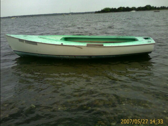
Right Ernie, my 11.5ft rowboat nice shape and not unlike the Irreducible actually. This week's effort as fun as it was, kinda confirms the YT being a bit big for it. If I lived on a lake, I might make it work but since the bay is right here, I should have a bay capable boat. Been looking at sail hulls but needs to be just the right look to justify the YT, no shortcuts. Here is a 15ft I was going electric with and even obtained an Etek motor for it, but then we moved and I gave the hull away. It's not perfectly vintage, but classic, maybe almost enough...
 |
bruce
Senior Member
Username: bruce
Post Number: 552
Registered: 07-2002
| | Posted on Friday, April 22, 2016 - 09:01 pm: |
|
Consider the wave peak intervals on the body of water you intend to use the hull on. Too short a hull and the bow will continuously drop over the peak of a wave and dive the nose into the next roller. Also a keeled hull will impede or at least slow the roll moment should the hull broach in the trough of a wave.
Head West to Mystic engine show in August with cash ; you may well find the engine suited for your lapstreak. |
russell
Senior Member
Username: russell
Post Number: 89
Registered: 08-2003

| | Posted on Friday, April 22, 2016 - 10:09 pm: |
|
Negativity on steroids? Love it. However, we haven't even got round to the size of prop you are gonna have to swing under there and the resultant angle the poor old donk is going to have to sit at......
I'd like to see a four horse Stuart Turner with reverse in there..... |
narrabay
Senior Member
Username: narrabay
Post Number: 91
Registered: 02-2016
| | Posted on Friday, April 22, 2016 - 10:45 pm: |
|
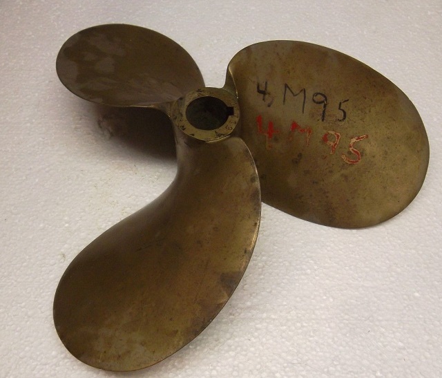
Hi Russ, the YT manual calls for a 12x10 prop. The test position of the YT allows for about a 48" shaft which would have to be 6" below the bottom at its end and 5"or so above at the flange. The bottom curves up but only slightly. I calculated previously that this would very approximately max out the 15 degree max engine angle. It really does however seem this engine-trans is just a bit too much for the hull. But it's fun to talk about here anyway. |
russell
Senior Member
Username: russell
Post Number: 90
Registered: 08-2003
| | Posted on Saturday, April 23, 2016 - 02:16 am: |
|
That sounds a smaller prop than I'd have expected. What revs does the engine do? |
miro
Senior Member
Username: miro
Post Number: 861
Registered: 11-2001

| | Posted on Monday, April 25, 2016 - 08:09 pm: |
|
Haven't visited lately, but a disappearing propeller type installation only needs one flex joint. The shaft speeds up and slows down with each revolution, but it's driving a prop so it doesn't really matter, and since the speed is relatively slow (RPM) the vibration won't be noticeable.
The low HP also helps keeps things from getting out of hand.
But I am inclined to agree that the YT might be too big for that hull.
A copper jacket Waterman or a St Larwrence would be better - straight shaft - no transmission needed since they can reverse on the switch - tilted engine is the usual installation (2 cycle).
I think I posted a video of an aluminum 14 ft boat with a St Lawrence - I'll see if I can retrieve it.
Miro |
miro
Senior Member
Username: miro
Post Number: 862
Registered: 11-2001
| | Posted on Monday, April 25, 2016 - 08:21 pm: |
|
Here's the link to the video.
https://www.youtube.com/watch?v=PdW6KPBwcBc
It shows him doing a test fit and also shows the stingers he used.
This should help you guage what you should consider. His boat is 14 ft - yours is a bit shorter -
If you are concerned about turning turtle - but still like the boat - add some outboard flotation on the outside of the hull - discreetly and artfully hidden of course.
Miro |
herbertchoover
New member
Username: herbertchoover
Post Number: 2
Registered: 04-2016

| | Posted on Saturday, April 30, 2016 - 10:45 pm: |
|
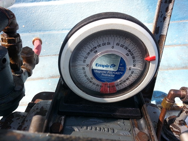
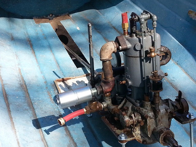
This just might work... have all materials for stringers, etc. Found a 11x12 prop, and using a angle finder, it appears that this engine can sit at a ten degree angle, around a 45" prop shaft, and swing that prop. I *might* need to "cup" the bottom by an inch or so at the prop area to keep the angle at or below 10 degree.
HH
 |
herbertchoover
New member
Username: herbertchoover
Post Number: 3
Registered: 04-2016
| | Posted on Saturday, April 30, 2016 - 10:49 pm: |
|
 |
jb_castagnos
Senior Member
Username: jb_castagnos
Post Number: 1154
Registered: 07-2002

| | Posted on Sunday, May 01, 2016 - 12:12 pm: |
|
Looks OK, sitting behind the engine will help weight distribution. It's not going to be a race boat, should putt around OK, have fun with it. |
herbertchoover
Member
Username: herbertchoover
Post Number: 4
Registered: 04-2016
| | Posted on Sunday, May 01, 2016 - 01:17 pm: |
|
Thanks JB. The tentative plan is to extend the rear seat forward another foot, with a back rest so the seating is just aft the transmission with steering lever or wheel on the side. old school storage crate for behind the back rest. under the seat and bow compartment have expand foam for buoyancy just in case.
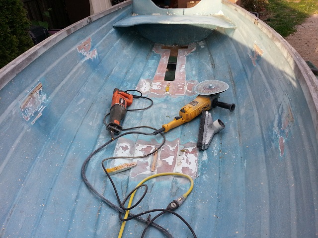
Much easier to do this with the seating out of the way. The stringers will probably be 3.5" high, 1.5" thick, transom to bow taper. Already procured the fiberglass resin, materials, and a 9" grinder with heavy sanding disks to prep the old work for that new work.
The little hull is surprisingly tough even without the original seats, which were drastically overbuilt and heavy anyway.. |
david_doyle
Senior Member
Username: david_doyle
Post Number: 59
Registered: 03-2013
| | Posted on Sunday, May 01, 2016 - 02:52 pm: |
|
The original designer might have considered the seats structure that helped support the sides and kept them from folding inward. You might want to work some structure back into the design. It would not take much.
You will need some flotation high up on the sides anyway to keep it from becoming very unstable in a swamped condition.
Glass does not float the way wood does. |
scott_n
Senior Member
Username: scott_n
Post Number: 273
Registered: 02-2008
| | Posted on Monday, May 02, 2016 - 12:32 pm: |
|
the shaft log shout come up thru the center of the boat with a stuffing gland at the top end and a cutlass baring at the bottom. you would wont to have this made up and in hand when you glass in your stringers and set shaft lineament also a couple of frames authorship would stiffen up the hull. |
herbertchoover
Member
Username: herbertchoover
Post Number: 6
Registered: 04-2016
| | Posted on Monday, May 02, 2016 - 12:49 pm: |
|
thanks guys. I have a shaft log, stuffing box, and prop should be here today. as to structure, there will be a pair of resolute stringers fiberglassed in to the boat at the width of the YT mounting flange.
as to side stiffness, first, the boat is amazingly strong already (made of hand-laid glass cloth) I have 2 choices, and I am leaning toward side stringers from the rear seat to the front. I can attach wood seats across them and move them if desired.
the other choice is two ribs glassed in tapering to the gunwales.
I'm ok on doing the structure and have been doing glasswork since I was about 12 or so, but locating the shaft log, and building the keel (which I want to protect the prop) and getting everything into alignment will probably take a few tries!
One thing, hoping to keep the shaft angle at or below 10 degrees. I may have to cup the bottom by an inch or so at the prop (very shallow tunnel). Also, the YT calls for a 12x10 prop or thereabouts. I swapped that and obtained a 10.5x12. There is a prop shop near me and I may ask them to take 1/4" off the blades to make it an even 10x12. That saves an inch of prop clearance below this small boat. The tunnel will save at least another 1"
that makes the tip of the prop and keel 2" shorter to the bottom, prop shaft angle less too.
I'll post pics and discuss any mistakes so others in the future can benefit.
Thanks for the inputs! |
jb_castagnos
Senior Member
Username: jb_castagnos
Post Number: 1156
Registered: 07-2002
| | Posted on Monday, May 02, 2016 - 01:48 pm: |
|
If you can figure the spot for the hole through the hull, start with a small hole, run a string line through, attach it to some "batter boards" clamped to the transom and bow. At the prop location adjust the sting for the clearance you need, do the same at the flywheel location. The string line will be your shaft location, engine mounts are usually about a 1/2" below this, thickness of the base. If you are not sure of the through hole location this can be mocked up outside the hull, the spot the line passes through the hull can be transferred over to the hull. |
miro
Senior Member
Username: miro
Post Number: 863
Registered: 11-2001
| | Posted on Monday, May 02, 2016 - 09:44 pm: |
|
I recalled that I had posted some pictures of another YT1 boat.
Here it is. I hope it shows that a large-ish engine CAN go into a small-ish boat.
http://www.oldmarineengine.com/discus/messages/4/7098.html
Miro |
herbertchoover
Member
Username: herbertchoover
Post Number: 7
Registered: 04-2016
| | Posted on Monday, May 02, 2016 - 10:14 pm: |
|
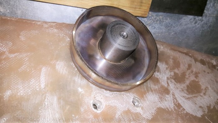
thanks Miro. incredible. and that was 2005, the man has been gone for 11 years. I notice a nice copper splash pan under the flywheel, and more significantly, electric start with a ring gear attached to the back of the flywheel.
nice boat wonder who has it now? |
herbertchoover
Member
Username: herbertchoover
Post Number: 18
Registered: 04-2016
| | Posted on Wednesday, May 11, 2016 - 05:00 pm: |
|
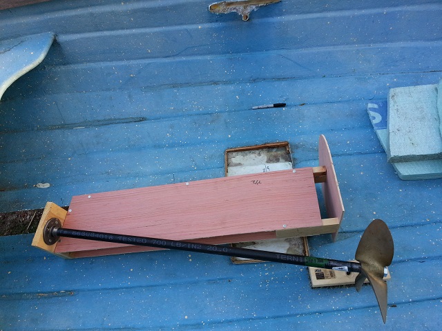
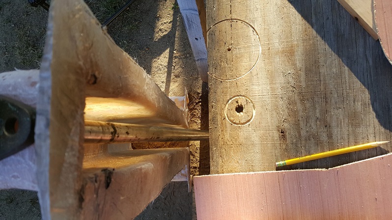
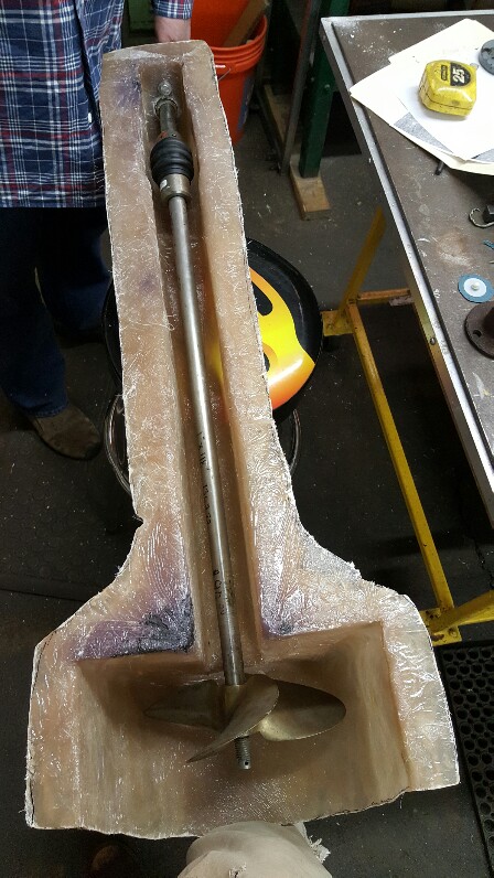
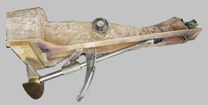
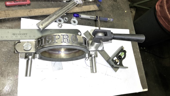
OK, well finally took the sawzall to it today! (And a drill, jigsaw, and circular saw)
The shaft is just over 48", but of course will be cut to accept the u-joint. The engine sits at just around 10 degrees which is my goal. The temporary flange has a little play so I supported the shaft at midpoint in that play.
What is interesting is that the setup seems much longer than the Dispro to get the prop to clear, maybe I'm using a bigger prop.
Could REALLY use some measurements of the dispro housing, actuator, prop diameter, and shaft length.
 |
david_doyle
Senior Member
Username: david_doyle
Post Number: 65
Registered: 03-2013
| | Posted on Wednesday, May 11, 2016 - 08:52 pm: |
|
Your on your way!
Any luck finding some cardboard and dowel/broom sticks to build this with in a beta version?
The measurements that you need are all going to be self generated at this point. I might go so far as to use chicken wire to form the housing, would support pivot points and allow easy tweaking in the early stages of design.
Thanks alot for sharing this adventure, really looking forward to your success. Do you have a nor'wester hat and a wooden lobster trap? |
herbertchoover
Member
Username: herbertchoover
Post Number: 19
Registered: 04-2016
| | Posted on Wednesday, May 11, 2016 - 09:10 pm: |
|
thanks dave, I plan to use luan plywood. from what I can see the device lever arm is two sides joined at the top and they come together again at the bottom skeg section. once I have the mock up made and working (plan to use rubber tube for a u-joint until can source a real one) my friend has a stainless steel fab guy who can quote me on making it outta metal. one real question mark is the pivot bolt design. a real dispro seems to have small end, medium square center, larger shoulder, and them some way to attach the handle at the head (square again?). I'll figure something out but a machine shop will almost certainly be involved. not afraid of making the housing, that just requires patience and be willing to get itchy. |
david_doyle
Senior Member
Username: david_doyle
Post Number: 66
Registered: 03-2013
| | Posted on Thursday, May 12, 2016 - 12:57 am: |
|
Why does the prop need to come up inside the hull? Have you thought thru having it rise outside the hull?
Your rudder can be offset.
On a dippy you needed it in the boat for a bunch of reasons but on your hull there is no need for it to be there, the more I think on it, the more I think you are making a mistake using a system that was developed for a doublender and trying to force it to work in short transom boat .
Where you have the prop box now You are already so close to the transom that you might as well reach over the stern to clear a prop as into a well. Also if you place it aft of the transom your lifting mechanism can have a SOLID anchor point (the transom).
Safer and more room if you raise it aft of the transom. |
herbertchoover
Member
Username: herbertchoover
Post Number: 20
Registered: 04-2016
| | Posted on Thursday, May 12, 2016 - 07:16 pm: |
|
thanks for the suggestion Dave but the path is set... I think it will be nice too. and here is a video (all in fun of course! 
https://youtu.be/5LUJF293-pg |
herbertchoover
Member
Username: herbertchoover
Post Number: 21
Registered: 04-2016
| | Posted on Thursday, May 12, 2016 - 07:32 pm: |
|
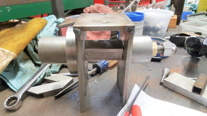
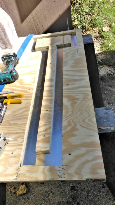
Today's effort, a mock-up of the "Dispro" housing, at 11 degree shaft angle the 11" prop just clears the bottom. I plan to narrow the tunnel to about 2" because based on specs, I dont need a 1" u-joint, can use even a 1/2" as the torque specs seem more than adequate.
 |
G. Roehl Sr.
Visitor
| | Posted on Thursday, May 12, 2016 - 08:50 pm: |
|
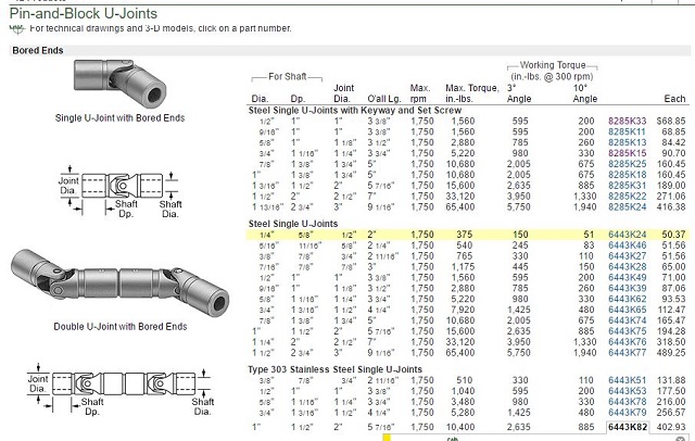
What size (dia) is your shaft? Methinks you would use a joint designed to fit it. The highlighted one is for 1/4" shaft....
I have no idea of the torque produced by your engine, but wouldn't it be more than 10 ft/lb? |
todd_vidgen
Senior Member
Username: todd_vidgen
Post Number: 268
Registered: 03-2008
| | Posted on Thursday, May 12, 2016 - 09:58 pm: |
|
That is very good. What happens if we have to invoke rule 4.
Cheers, Todd |
giii
Member
Username: giii
Post Number: 10
Registered: 04-2010
| | Posted on Thursday, May 12, 2016 - 10:15 pm: |
|
Ratings are in in-lb in the chart. |
david_doyle
Senior Member
Username: david_doyle
Post Number: 67
Registered: 03-2013
| | Posted on Friday, May 13, 2016 - 03:33 am: |
|
That Captain (in your video) ended up hypothermic in a deflated raft...... IIRC he was only captain to begin with because his boyfriend was a rich south American drug lord and for the most part absolutely no one liked or respected him (except for maybe the pill junkie). |
herbertchoover
Member
Username: herbertchoover
Post Number: 22
Registered: 04-2016
| | Posted on Saturday, May 14, 2016 - 07:45 pm: |
|
dave, lol great points!
g roehle, as to the u-joint, no idea why that one is highlighted. I was considering the 5/8" joint which should spin inside my 2.25" wide channel but still have enough strength. the 3/4" rated at 40ft lb at 10degree angle, and 118ft lbs at 3 degrees, and 660ft lbs at 0 degrees. My old supercharged V8 didnt make that kind of torque. in plain steel, the 3/4" costs $112. but this is all up in the air and I am open to suggestions.
Maybe I'm being cheap but the IDEAL joint is the 1" in 303 stainless, at $400, is too much for me to justify. for just over a hundred bucks, the 3/4 plain steel gets this running and seems to have enough torque (while the engine makes only a few ft lbs itself, I have no idea what peak torque it sees with each firing of the cylinder, or when the prop inevitably strikes something).
also, did some grinding today, the bulk of the prep to bare fiberglass. the hull has some epoxy coating or maybe gel coat over the gel coat, quite thick. spent about an hour grinding and with vacuuming up the dust after. wore a white tyvek suit, filter mask, and eye goggles. I'm still itchy. the borderline dangerous 5.3HP 9" dewalt grinder I got from Craigslist helped minimize the time involved, to say the least!
have a nice Sunday everybody
 |
miro
Senior Member
Username: miro
Post Number: 870
Registered: 11-2001
| | Posted on Thursday, May 19, 2016 - 07:53 am: |
|
The DisPro uses a 3/4 in shaft and the joints only break when they are very very old, and rusted, and the prop actually hits something. This is not a very common because the skeg usually hits first and protects the prop.
The joints ( steel) usually wear out after 25 years of active use.
The joint in my own boat is about 40 years old and still not "wobbly" . I use the boat almost every weekend in the summertime.
Looks like you are doing a good job.
miro |
herbertchoover
Member
Username: herbertchoover
Post Number: 23
Registered: 04-2016
| | Posted on Friday, May 20, 2016 - 01:30 am: |
|
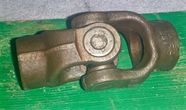
miro, thank you , very very helpful. does your boat have a rubber cutlass style shaft bearing, or something else?
can you possibly take some close up pics of the actuator arm, prop bearing, u joint, and the pivot bolt? a handful of pics of that stuff would really help. also, how long is the propeller shaft and the actuator arm?
I can estimate all this from the pics in my Dispro book and other places, but have no actual clear pics of the arm, etc...
tonight after work I was looking at pin-block u joints. a 1" regular steel is about $200, and SS is $400. (remember I have salt water here) but since you run 3/4" with no troubles, I could always drop to that and lower the u-joint cost. my prop is 1" so I may as well stick with 1" shaft but have the ends at the u-joint turned down to 3/4". the ONLY reason for this is to save money, as I am far from rich.
was tempted to grab this (below) for mock up and maybe use it til it breaks, but again, salt water so asking for trouble. just not sure what to do about a u-joint.
http://www.ebay.com/itm/Hi-Angle-PTO-U-joint-Assy-1-0-Inch-Bore-/162071335195?hash=item25bc34511b:g:d9YAAOSwubRXOB3j&vxp=mtr |
herbertchoover
Member
Username: herbertchoover
Post Number: 24
Registered: 04-2016
| | Posted on Friday, May 20, 2016 - 01:48 am: |
|
 |
herbertchoover
Member
Username: herbertchoover
Post Number: 25
Registered: 04-2016
| | Posted on Friday, May 20, 2016 - 01:59 am: |
|
There is also this one but not sure how it is made, is it all stainless? Also still really expensive...
http://www.amazon.com/gp/product/B0081TIE96/ref=s9_hps_bw_g328_i4 |
miro
Senior Member
Username: miro
Post Number: 872
Registered: 11-2001
| | Posted on Monday, May 23, 2016 - 10:15 pm: |
|
I'm not ignoring you but it's a challenge to find the parts to photograph out of a device.
The cutlass bearing is bronze water lubricated.
The joint you show is the same style but steel versions are generally used. It has to be small because there is very little room in the device for a flex joint.
miro |
herbertclarkhoover
New member
Username: herbertclarkhoover
Post Number: 3
Registered: 05-2016

| | Posted on Friday, May 27, 2016 - 06:33 pm: |
|
thank you miro, whatever you come up with will be appreciated.
here's the latest housing mock up.
 |
kayak
New member
Username: kayak
Post Number: 2
Registered: 06-2016
| | Posted on Monday, August 01, 2016 - 02:21 am: |
|
just a quick update, and btw my sign on has not worked right in months, no emails come thru. so I created a new sign on and still no emails, so its not me. I emailed the admin but no help there, maybe he's busy with other things I dont know. just glad this board is up and working even without email notifications.
anyway, I have been sidetracked on another project which is almost finished. but meanwhile I have the housing mock-up in the hands of a fiberglass craftsman. but despite initially being enthusiastic, he doesnt seem to be getting to it (he is very busy with his regular work). the YT1 sits on my bench waiting for reassembly, everything laid out nicely. and as to the retractable strut assembly, I also have someone who wants to mock something up for that and if it seems good, make a real one in stainless.
I guess I wasnt kidding when I mentioned sea trials NEXT year this should be nice whenever it's done however. |
miro
Senior Member
Username: miro
Post Number: 879
Registered: 11-2001
| | Posted on Saturday, August 06, 2016 - 09:20 pm: |
|
Chris - this is the path that many of us have followed.
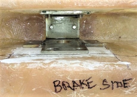
The boat that I recently made the engine bed for, has been a work in progress for well over a decade.
Life does intervene, but patience seems to be a requisite for this past time.
And what's even better is when you finally get 'er done, and you and a friend go for a ride.
It's really sweet.
Miro |
kayak
Member
Username: kayak
Post Number: 5
Registered: 06-2016
| | Posted on Sunday, August 07, 2016 - 10:38 am: |
|
Thanks Miro, very much appreciated. |
kayak
Member
Username: kayak
Post Number: 7
Registered: 06-2016
| | Posted on Tuesday, August 09, 2016 - 08:42 pm: |
|
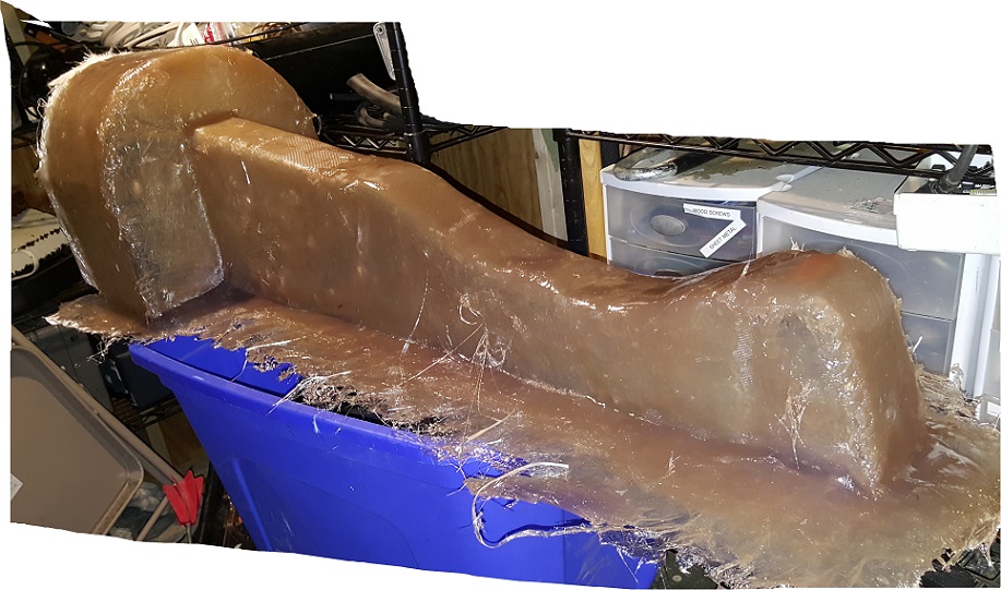
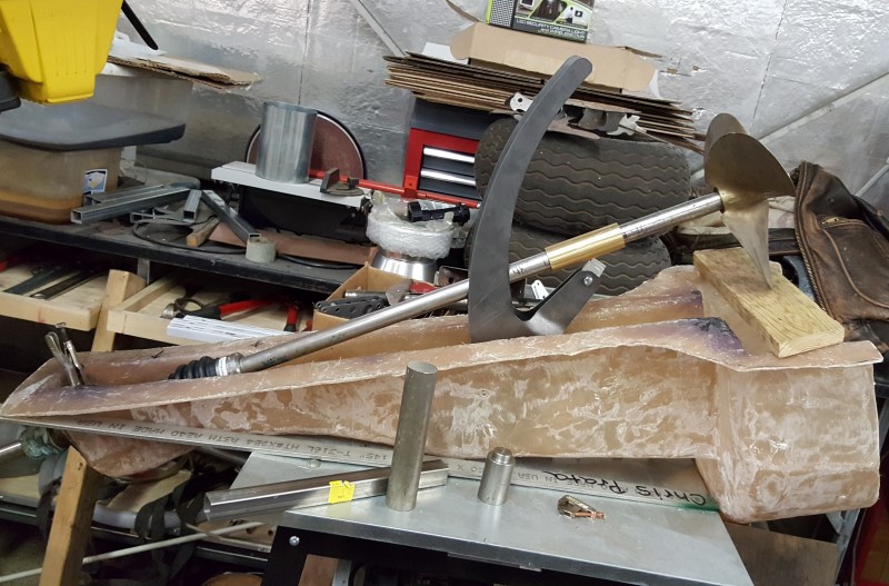
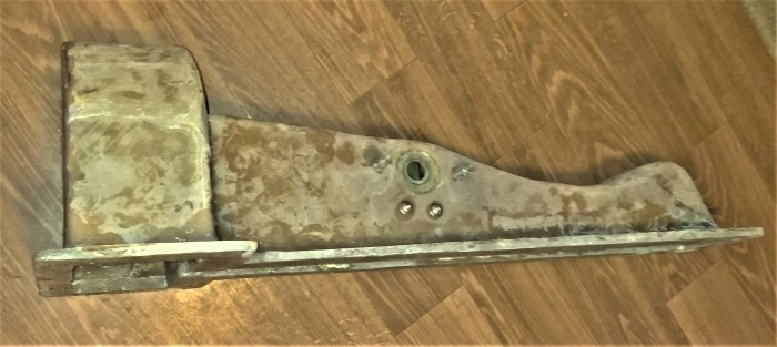
Well today I bit the bullet and tortured myself with fiberglass work. It's not pretty (yet) and not efficient (has high resin percentage), BUT it will do. Trim the flange, take to it with minigrinder, more layup where needed, and then mock up the "device" for my machinist/fabricator. This *could* be the first "Dispro" unit manufactured in 60 years. Probably not, but could be!
As to the process, I stapled a garbage bag to the wooden "plug" mold, and started laying up mat which de-bonds in the presence of polyester / vinylester resin. That made it compliant enough to push into the compound curves. Then I layered cloth everyplace and much more where more strength would be needed especially the snout, device bearing location, and the flange areas. The plug was EASY to pull out, surprisingly so.
 |
david_doyle
Senior Member
Username: david_doyle
Post Number: 69
Registered: 03-2013
| | Posted on Tuesday, August 09, 2016 - 09:46 pm: |
|
ccol, will you add a flange where the prop housing mates with the transom? |
kayak
Member
Username: kayak
Post Number: 8
Registered: 06-2016
| | Posted on Tuesday, August 09, 2016 - 09:59 pm: |
|
dave, no decided to glass that in when installing it. for one thing the seat above is in the way. and it would have been just another angle to work with on the build up. will rough it up and add a 2" wide double flange with many layers at install. that stage may be coming fairly soon. |
david_doyle
Senior Member
Username: david_doyle
Post Number: 70
Registered: 03-2013
| | Posted on Wednesday, August 10, 2016 - 03:20 pm: |
|
Well you sure got my wheels spinning thinking about
the possibilities you are exploring. Very neat to see just how well it is coming together. The next ones will be a breeze for ya.
Please share your journey in getting the device's innards built up.
I think your a lot closer to success in-terms of being fit for sea then it might feel. That said hopefully in the meeley of getting it all buttoned up you will have time to snap pics etc.
Hope the momentum continues eager for the next installment
Thanks |
kayak
Member
Username: kayak
Post Number: 15
Registered: 06-2016
| | Posted on Friday, August 26, 2016 - 07:40 pm: |
|
thanks Dave. more slow progress today. btw I finally more or less finished the teardrop camper and we stayed in it at an airshow I was invited to last weekend (why I wasnt at Mystic).
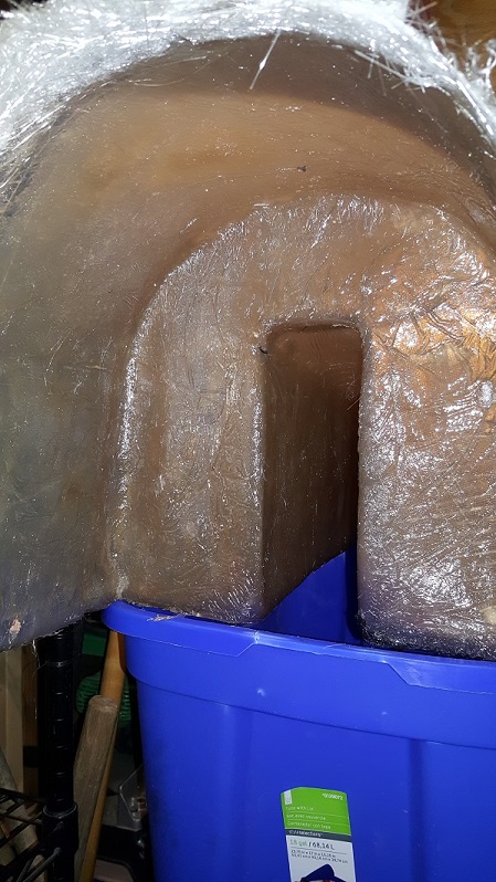
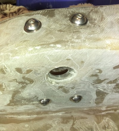
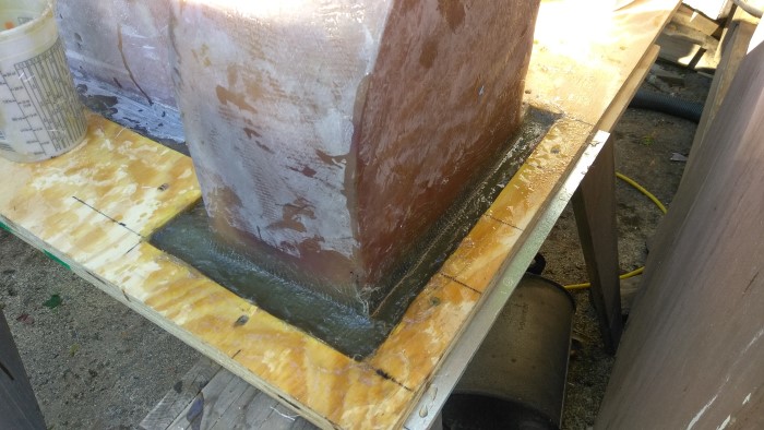
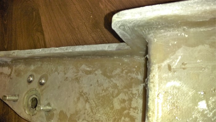
so today I dragged the housing out and its so wonky (which, is actually ok) that the stuffing box obviously would not align, so I pondered and realized that I can bed the stuffing box in wet fiberglass mat with the shaft sticking through at the correct angle, so that when the glass hardens, the new stuffing box flange mounting surface will be at the right angle and will align the flange properly. (one hopes anyway!)
 |
kayak
Member
Username: kayak
Post Number: 16
Registered: 06-2016
| | Posted on Friday, August 26, 2016 - 08:11 pm: |
|
 |
kayak
Member
Username: kayak
Post Number: 22
Registered: 06-2016
| | Posted on Friday, October 14, 2016 - 12:06 am: |
|
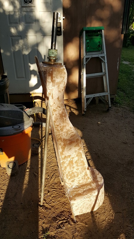
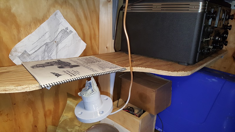
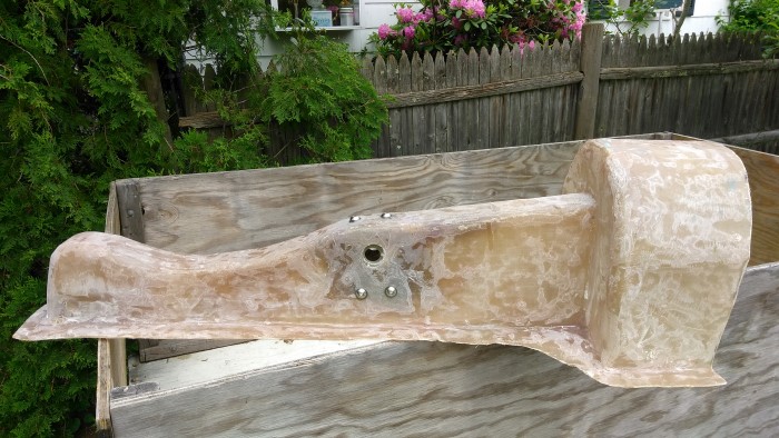
After finishing the teardrop camper and taking it on a 3000 mile maiden voyage, time to get back to the YT-1 project. A few days ago, dug out the workbench and cleared it for this. Tonights effort, scrape, degrease, prime, and paint the front housing - carefully - since it is inadvisable to attempt to remove the camshaft.
 |
david_doyle
Senior Member
Username: david_doyle
Post Number: 79
Registered: 03-2013
| | Posted on Friday, October 14, 2016 - 01:06 am: |
|
Cure that in a cardboard box with a light bulb for heat. Assuming your wife wont let you put in the oven over night. (just do not burn down the shop as I am selfishly looking forward to seeing this project come together this winter) |
kayak
Member
Username: kayak
Post Number: 24
Registered: 06-2016
| | Posted on Friday, October 14, 2016 - 11:03 pm: |
|
thanks dave, it's 50% done with 200% to go! biggest upcoming challenges that I can think of are fiberglass structure (stringers, ribs, etc), and the lever arm of the Dispro-like device. Beyond that it still wont be easy (for me) to manage plumbing such as the keel cooler loop through hulls, and mounting the jabsco pump for exhaust cooling water. The fiberglass scares me the most wish i had Ernie's fiberglassing skills for example, his work on the fantail engine bed is very clean and correct. |
imotorhead
Member
Username: imotorhead
Post Number: 11
Registered: 05-2016
| | Posted on Saturday, October 15, 2016 - 12:06 am: |
|
Really cool... !! Neat boat! |
kayak
Member
Username: kayak
Post Number: 25
Registered: 06-2016
| | Posted on Wednesday, October 19, 2016 - 04:18 am: |
|
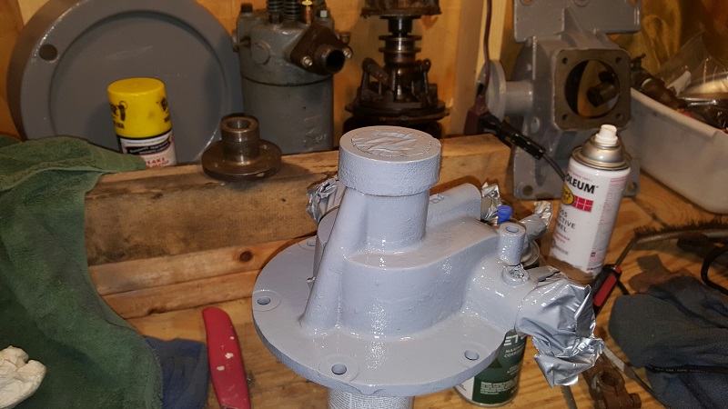
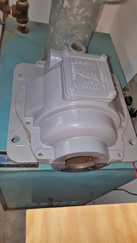
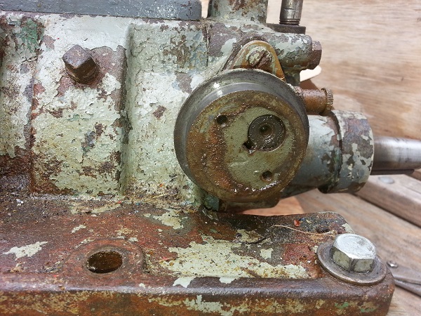
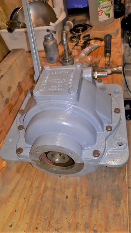
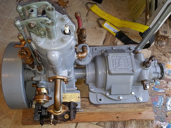
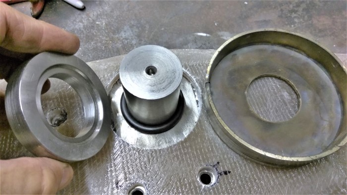
couple more pics, getting ready for reassembly of the YT and gearbox. Larger castings were sandblasted and epoxy primed before painting, smaller parts manually scraped and cleaned with non-resedue CRC brake cleaner and primed with self-etching primer before paint. I actually wish the paint was low lustre and not so shiny. but still way better than the crud covered occasionally rusty castings I started out with.
This is a disassembly, cleaning, visual inspection, repaint, and reassembly with new seals.
Gearbox with new oil seal
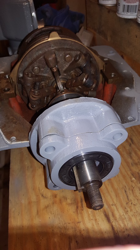
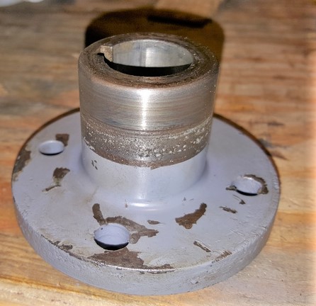
Output flange (sealing surface masked off)
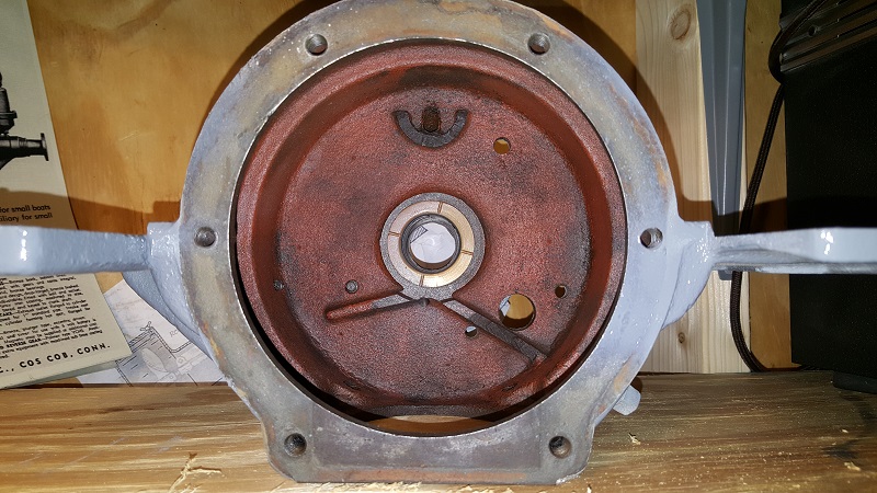
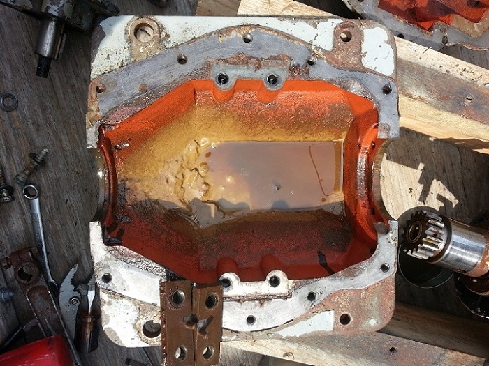
Inside the crankcase showing the red lead paint applied by the factory to control casting debris. that is best left alone but a replacement paint is available I have seen somewhere.
Front cover with camshaft
 |
kayak
Member
Username: kayak
Post Number: 28
Registered: 06-2016
| | Posted on Tuesday, October 25, 2016 - 04:05 pm: |
|
a little update. I sourced the SAE30 non-detergent oil at Tractor Supply - $20 for a 2 gal jug - and that also goes into the FNR transmission.
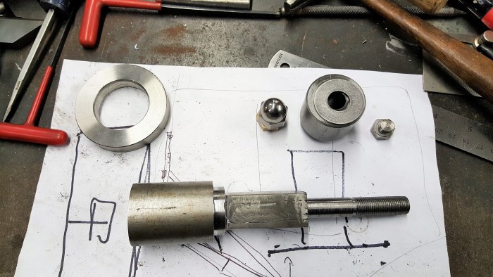
just waiting for the correct crankshaft oil seals - they had sent the wrong ones. correct style and I.D. but O.D. was small. new ones coming this week. hopefully I assemble this YT correctly, its simple as a lawnmower engine so I dont see why not. As to the running gear, I have a plan to measure for the two prop shafts (short front one, and main one) and get it cut, checked for true, and a keyway cut. While at it I need to source a companion flange and have that mated. Then only remaining technical challenge will be the "device" arm, and especially everything at the hinge/pivot point which has to be a water seal, allow an arm with lot of leverage to be attached, and have minimal play in any direction since it is what steadies up the wheel (prop) out back and we dont need that moving around. But first things first, engine together back on the oak test bed, and test run.
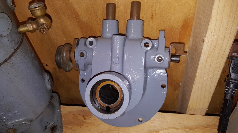
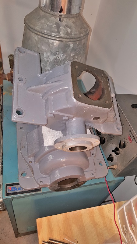
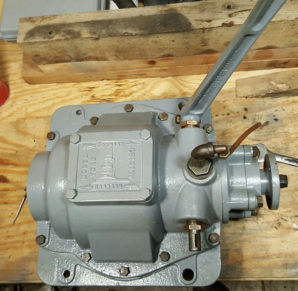
Here's a couple pics of the beautiful housings, blasted (outside only), epoxy primed, painted gray. Just amazing looking design from 1921, almost 100 years ago now. Warren Harding was president at the time the YT was designed by Palmer!
 |
david_doyle
Senior Member
Username: david_doyle
Post Number: 88
Registered: 03-2013
| | Posted on Tuesday, October 25, 2016 - 04:56 pm: |
|
Kayak,
If you look at one of the online indexes for Model Engineer Magazine you will find some interesting articles on the construction and use of Universal Couplings/Joints.
Also lots of novice level articles on spline and keyway cutting etc.
I know your gonna rely on the kindness of others but a 200 dollar lathe and a hunk of HSS and you'd be in command!
Looks like your getting the paint nice and hard. Cannot wait to see if all sitting in a boat with the device. Keep up the good work. |
david_doyle
Senior Member
Username: david_doyle
Post Number: 89
Registered: 03-2013
| | Posted on Tuesday, October 25, 2016 - 05:06 pm: |
|
Just looked on your local craigslist. Gee whiz no wonder you can find local help with the project seems like everyone in you nieghbourhood must have a lathe in the shed. Anyway here is a 200 dollar lathe handy to you. (or maybe 50-150).
Swap out the SS for cold rolled and use the savings in material and labor to start your next project!
https://images.craigslist.org/00S0S_7r50NOOAw76_1200x900.jpg |
kayak
Member
Username: kayak
Post Number: 29
Registered: 06-2016
| | Posted on Tuesday, October 25, 2016 - 09:01 pm: |
|
thanks dave, actually I dont have the space for a lathe, and it wont cut a keyway. the last time this came up, I had found a miller/lathe that was interesting but it got sold almost instantly. however, I also dont know how to run a lathe and a miller and people spend years under the eye of a journeyman to get good at that work.
wouldnt have had space for it anyway. BUT I went on a trip recently and met a guy who started telling me about adding a 1974 mercedes a/c compressor to his truck. "why?" I asked, and he said to make air pressure. "why" and he said for the train horns and pulled a key fob out pressed the button and it did sound like a locomotive was coming into the building!
"why?" you ask do I bring this up? because he went on to tell me about "builder spaces" he was involved with. here is what he is talking about:
http://www.techshop.ws/ |
david_doyle
Senior Member
Username: david_doyle
Post Number: 90
Registered: 03-2013
| | Posted on Tuesday, October 25, 2016 - 09:44 pm: |
|
A lathe will with out a moments hesitation cut a Key way! internal or external. You can read about it and set up the cut and make the cut faster then you can drive to a buddies house.
Splined shaft just as easy. (assuming the number of splines will divide into one of your changewheels or bull gear evenly)
FYI my lathe is in the kitchen....... I live in a very small space. Ideal no but better then the alternative! Lathes do not take up much space especially if you loose the countershaft and drive with a reversible DC motor with speed control. That said 9.5 tenths of anything useful that you do with a lathe is/can be done turning it by hand so you can leave the motor out of the equation. Your keyways/splines are hand powered cuts.
Come to the dark side!
You know i just tease you cause your obviously a bit of a mad scientist type lol |
kayak
Member
Username: kayak
Post Number: 30
Registered: 06-2016
| | Posted on Wednesday, October 26, 2016 - 03:57 am: |
|
OK Dave, I just watched a few you-tubes showing key-way cutting using a lathe. Very simple for sure! I would never have guessed to use the lathe not turning and the tool transport(?) looks to be moved by hand by the operator, cutting 2 thousandths at a time and in one he used a dial indicator to be precise.
I also watched a video on drilling square holes (can be done with a drill press). I had NO IDEA about this stuff. Can a lathe be used to mill things too? (Using the chuck to hold a cutter and the transport to move the part?
Very interesting. With a lathe and a square hole cutter I could make the pivot piece for the device.
I wonder if working with stainless is any harder or requires different material in a cutter???
With a lathe and some skill, I could make the companion flange? Could I use it like a drill press to bore the four flange bolt holes?
https://youtu.be/rjckF0-VeGI
https://youtu.be/XcU0LTavzDM
EDIT: answered my own question, basic milling on lathe:
https://youtu.be/i2cgoPpCmPc |
kayak
Advanced Member
Username: kayak
Post Number: 31
Registered: 06-2016
| | Posted on Wednesday, October 26, 2016 - 04:54 am: |
|
Found this what u think? I can build a lathe shed I suppose (very small shelter for it) also not sure if it needs 3 phase power.
http://providence.craigslist.org/tls/5826794598.html |
david_doyle
Senior Member
Username: david_doyle
Post Number: 91
Registered: 03-2013
| | Posted on Wednesday, October 26, 2016 - 11:13 am: |
|
Yes stainless is more difficult but you do not need (or one could argue want) to use stainless. You want to keep material cost to about zero using steel. If you need convincing maybe some time with a cathodic table?
Square holes can be shaped like the keys or splines but the fastest, easiest way to make a round hole square is with a file.
Yes you can mill with single point or multi flute tools held in the chuck and the work held in a variety of ways on the saddle. Lots of drawbacks but doable. Action books (available at every library) has a book "milling in the Lathe"
Of course the flange is a lathe job that you could do. Not sure how big the flange is but you for sure could do it. You might end up bolting a hand drill to the saddle or maybe you would spin the flange. You'd figure that out in short order.
The lathe in your link: I can think of worst things to spend money on but I would not want to steer you wrong on something I cannot touch to judge. (yes you need the changeweels/gears)
OK now before we get too far down this road. Do some reading on basic lathe saftey. Your looking at a signifigant tool there and it is possible to mangle yourslef pretty good if you do not start off with a bit of fear/respect. Compared to that 10 inch I play with a baby and yet I rely on fear to keep me moving real slow and thoughtfully but respect and sobriety would be sufficient to keep things fun.
Keep in the back of your head that some guys, in some places, at sometimes are able to pay for thier own hobbies/fun by using a lathe to work on other peoples needs.
Cheers |
david_doyle
Senior Member
Username: david_doyle
Post Number: 92
Registered: 03-2013
| | Posted on Wednesday, October 26, 2016 - 11:19 am: |
|
Just a couple more quick thoughts. You will absolutely need a bench grinder and a handful of HSS blanks. Not a big cost but you need to have em.
Do not start thinking about using any thing other then HSS.
Do not use too much you tube for education you need to get some books. |
kayak
Advanced Member
Username: kayak
Post Number: 32
Registered: 06-2016
| | Posted on Wednesday, October 26, 2016 - 03:00 pm: |
|
dave thanks all good advice especially the safety stuff. last time I ran a lathe was in middle school and I recall the safety lecture how cuttings can form a ribbon and grab you, spinning things can pull hair and shirt sleeves, stuff can fly into your eye before u know it. a LOT of power there, flesh wouldnt even slow it down 1%.
that being said, HSS - high speed steel. what do u mean by HSS blanks? for the work such as making the flange, or for other uses with the lathe? |
david_doyle
Senior Member
Username: david_doyle
Post Number: 93
Registered: 03-2013
| | Posted on Wednesday, October 26, 2016 - 03:58 pm: |
|
High speed steel blanks are the hunk of high speed steel that you grind your cutting tools out of. The other way to go is to you use special holders and inserts (carbide etc) that are pre formed. You will more trouble having success using the inserts and you will spend a fortune getting tooled up. If you stick with the HSS and grind your own turning, boring, threading tools you will not spend much of any money and have success in your turning.
Even excellent quality HSS is affordable and easy to come by.
Your flange will be easy you will do some outside turning and some boring and you will index the holes and mark thier location by counting gear teeth.
Get down to the library and get an OLD book. Maybe something written by Martin Cleeve (?). |
miro
Senior Member
Username: miro
Post Number: 888
Registered: 11-2001
| | Posted on Wednesday, October 26, 2016 - 07:57 pm: |
|
kayak, you are doing just fine - keep doing it - david advice is sound -
I found that it's useful to make some attempts just to get some experience and the feel of what you're doing before doing the "real" one. I inevitably thought of a better way to do stuff, AFTER I made something
Make mistakes early and often. If the maker spaces around you are anything like the ones near me - they are great !
miro |
kayak
Advanced Member
Username: kayak
Post Number: 37
Registered: 06-2016
| | Posted on Sunday, October 30, 2016 - 12:34 am: |
|
OK, I did reply to a lathe ad, but typically of craigslist, no response. That's probably a good thing, I have too many irons in the fire and just need a couple things machined now.
Tonight, I reassembled the transmission (a couple times!). Using permatex #82194 instead of gaskets where possible.
It looks great, but the shift carrythrough shaft is pitted, as is the output flange. I would like to get both remade new, and they are simple parts. Also, the carrythrough shaft (my name for it) is in brass bushings with no seals. IF they leak, then I would like to have new bushings made with grooves for oil seals.
Here are some old and the new pics:
 |
kayak
Advanced Member
Username: kayak
Post Number: 38
Registered: 06-2016
| | Posted on Sunday, October 30, 2016 - 12:39 am: |
|
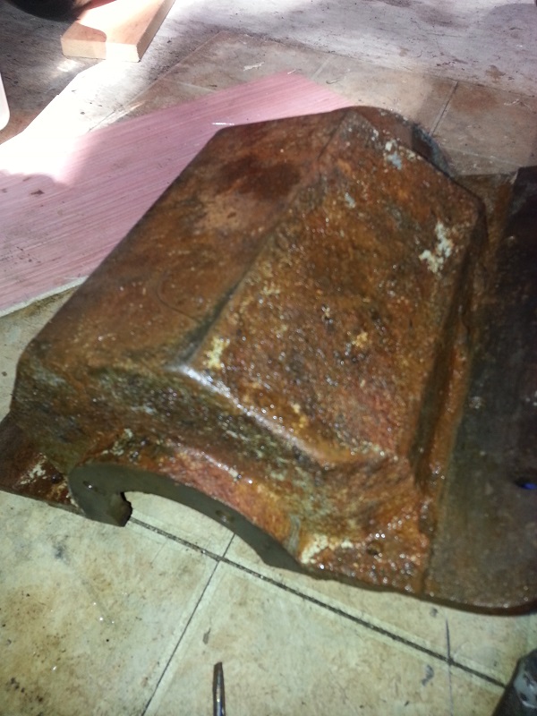
here are a couple more, the inside of transmission yuck! and the output flange, which either can be turned down, or replaced. yes dave I know I should get a lathe! ;)
 |
kayak
Advanced Member
Username: kayak
Post Number: 39
Registered: 06-2016
| | Posted on Sunday, October 30, 2016 - 12:45 am: |
|
 |
david_doyle
Senior Member
Username: david_doyle
Post Number: 95
Registered: 03-2013
| | Posted on Sunday, October 30, 2016 - 02:32 am: |
|
Dang you must be pleased as punch with your self!
So how many times tonight did you make a puttputtputtputtpuut noise while operating the lever?
Big thanks for posting all the pics and sharing the enjoyment of your project, it is generous and appreciated.
Send along an email to me if you can. I have some resources you should own. |
david_doyle
Senior Member
Username: david_doyle
Post Number: 96
Registered: 03-2013
| | Posted on Sunday, October 30, 2016 - 11:40 am: |
|
Kayak, be patient on that purchase- I just this morning bought a production Schaublin for $225, and last week a little Lorch for a jar of plums. Deals are out there. |
kayak
Senior Member
Username: kayak
Post Number: 62
Registered: 06-2016
| | Posted on Friday, November 11, 2016 - 11:19 pm: |
|
hi dave thanks again for pushing the lathe idea and for all the offline info, hadnt even heard of bench top lathe options. the grizzly 8x16 and 10x22 are interesting. engine almost ready for a test run finally. then back to the boat.
 |
kayak
Senior Member
Username: kayak
Post Number: 63
Registered: 06-2016
| | Posted on Saturday, November 12, 2016 - 05:46 pm: |
|
Well my hand has a blister and couldn't get it running! Almost though. I've had it fire a lot but just once each time and sometimes one more revolution on its own, has good compression. Initially the timing was too advanced and it kicked backwards. Cleaned the spark plug, tried a bit of ether, it pops, wont run. I will get it eventually, have to develop the knack, how much prime, how to turn it, where to start the turn, how fast. I have noticed that pulling the peg from about 5 oclock (counterclockwise) smoothly through TDC seems best.
Also revamped the buzz box a bit, added a marine pull switch and improved the connections. It is using Ernie's design from another thread and makes a very hot blue spark shown here:
https://youtu.be/nVdiJNkMH8A
 |
kayak
Senior Member
Username: kayak
Post Number: 64
Registered: 06-2016
| | Posted on Saturday, November 12, 2016 - 05:49 pm: |
|
and I just thought of yet another use for a lathe... adapt a little rubber tire to a small starter and set it up with a lever so it can be pushed against the flywheel. No more blisters! ;) |
kayak
Senior Member
Username: kayak
Post Number: 72
Registered: 06-2016
| | Posted on Friday, November 18, 2016 - 11:10 pm: |
|
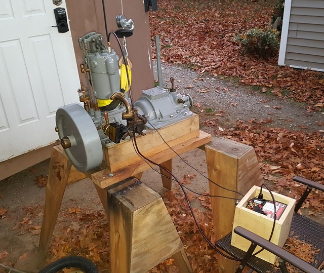
OK, it runs. Oiled it, primed. Had a heck of a time and my arm got tired. Switched to ernie's "kick it over" method, was just about to give up, Only ran for 23 seconds due to no water hooked up when it went finally. Just ran it briefly to clear the combustion chamber of assembly oil and prove everything is in alignment (timer, cam). Need to make a tank again and a water tank of some sort and give it a really good run. Also, I am trying to determine the RPM of the run. There is an "acoustic tachometer" app I put on my phone but it doesnt go below 500rpm. Not sure how good it would work anyway may use another tool on the PC.
https://youtu.be/Fv3dyCGrUDs |
david_doyle
Senior Member
Username: david_doyle
Post Number: 103
Registered: 03-2013
| | Posted on Friday, November 18, 2016 - 11:44 pm: |
|
Congrats that was a nice reward for your efforts. You must be pleased!
Now get to work on the device! |
kayak
Senior Member
Username: kayak
Post Number: 73
Registered: 06-2016
| | Posted on Saturday, November 19, 2016 - 01:31 am: |
|
Ok checked with a BPM (beats per min) app on my phone but I do not trust, but you can kind of tell by sound (120bpm would be 2 per second), RPM is obviously twice the bpm on a four stroke. I am estimating that it was 200bpm early and more later so i was not idling which i would guess is around 100 to 150 rpm as per this engines 800rpm red line and heavy flywheel, rather running at operating speed or more.
I dug out my cheap non-contact tachometer I got from ebay last spring (for this project) where you put a little piece of reflective tape on the flywheel and point this device at it and it reads out the rpm and will try that next.
I will get a fuel tank and water supply going and try to get the idle as low and steady as possible and take some readings and a video and post the video with the rpm stated so others can see and hear what low rpm sounds like. I really couldnt find that on youtube but there's millions of videos with all different descriptions.
As to the device Dave, I am still considering bench lathe options. One task that is very important (if miserable to do) is the boat needs some structure in the form of good stringers and maybe a couple ribs or partial ribs to be built in. This is one task that I would GLADLY pay for. 20 years ago had a high performance boat that we beat the stringers out of, I tried to make them myself and they really werent that nice so I happened to know someone at a fiberglass manufacturer who did side work. His stringers were like factory. They came out really tough and nice too. I need to find someone like that now. |
kayak
Senior Member
Username: kayak
Post Number: 95
Registered: 06-2016
| | Posted on Wednesday, January 04, 2017 - 08:26 pm: |
|
OK, well I havent posted in a while so here's a little update in case this project has any followers. Today was unseasonably warm, so I decided to try to run the YT1 with a modern carb for now to get it to warm up fully and so I can change the oil. I could not get it stable below 500rpm so thats where I ran it. It would get down to 350 but only for 15 seconds or so. When I get the original Zenith carb squared away that should help with this.
BTW in the video you may note that the drip oiler is in the off position. I had it set too fast so was cycling it on/off this run. And the engine was level so the crank splash was getting to both mains equally anyway.
This is what 500RPM sounds like. BTW, I verified the tachometer by analyzing the sound using stuff I learned in school as a kid, see pic.
I am STILL having big problems with oil from the breather going everyplace. It was not overfull either. The breather was functioning properly as a check valve when off the engine. If its a little blow-by, then hopefully the new cylinder if George makes some, and fresh rings will resolve that.
enjoy.
https://youtu.be/D2cGmjG0KTA
 |
kayak
Senior Member
Username: kayak
Post Number: 96
Registered: 06-2016
| | Posted on Wednesday, January 04, 2017 - 09:13 pm: |
|
Palmer YT-1 at 375 RPM (lowest i could get, and not for long)
https://youtu.be/NQis2TJQo_4
And at around 800 RPM - which is maximum recommended RPM per Palmer documentation. Not very fast huh?
https://youtu.be/lEDl5epPz2s |
kayak
Senior Member
Username: kayak
Post Number: 97
Registered: 06-2016
| | Posted on Friday, January 06, 2017 - 10:26 pm: |
|
Hopefully everybody enjoyed the YT run videos. As of today, I have toured two old school machine shops, one because he had a lathe for sale (too small), very cool shop and he does amazing work including cutting gears. The other one will be assisting by making the parts with me, starting with the companion flange, parting the propeller shaft and adding keyways for the u-joint, and making the cutlass housing with attachment ear. The last part (and probably the trickiest) will be to make the device lever arm. So this project slowly is moving along. |
kayak
Senior Member
Username: kayak
Post Number: 101
Registered: 06-2016
| | Posted on Friday, January 13, 2017 - 04:26 pm: |
|
Today we cut the 1" propeller shaft, and test fitted with the universal joint into the rough housing. Also cleaned up the pitted Palmer tranmission flange oil seal surface took about 20 thousanths to do that.
Next week its cutting keyways and starting to buld the device arm and cutless holder.
 |
ned_l
Senior Member
Username: ned_l
Post Number: 81
Registered: 08-2012
| | Posted on Monday, January 16, 2017 - 09:49 pm: |
|
Very nice. |
kayak
Senior Member
Username: kayak
Post Number: 102
Registered: 06-2016
| | Posted on Monday, January 16, 2017 - 10:00 pm: |
|
thanks ned
that is a u-joint for PTO applications, ordered from mcmaster carr. PN: 6443K75 (I think) and the optional rubber boot. I could (should) have got stainless but that would have been VERY expensive. the 1" shaft, big u joint, is over built but with the YT1 running 205lbs, a couple extra pounds of shaft etc didnt seem to matter. the boat may turn out to be too small. but then it wont be hard to transfer everything to a larger hull later if needed. |
kayak
Senior Member
Username: kayak
Post Number: 103
Registered: 06-2016
| | Posted on Wednesday, January 18, 2017 - 07:21 pm: |
|
The 316 stainless and a bloater cutlass bearing is waiting for me to pick up. going to build the lever arm and cutlass holder first, hopefully this week. skipping the skeg section until everything else done. may have enough prop shaft leftover to make the pivot pin outta that. |
kayak
Senior Member
Username: kayak
Post Number: 104
Registered: 06-2016
| | Posted on Wednesday, January 18, 2017 - 07:22 pm: |
|
I should add that Miro's Dispro device parts pictures and video are extremely helpful so thanks again Miro! |
miro
Senior Member
Username: miro
Post Number: 895
Registered: 11-2001
| | Posted on Monday, January 23, 2017 - 07:45 am: |
|
You are lucky that you can still work during the season where the water turns hard i.e. ice.
I was up to my place this past weekend and in spite of the arm weather and rain, the ice on the lake was about 10 in. More to co=me.
Glad to see the progress on your boat.
miro |
kayak
Senior Member
Username: kayak
Post Number: 106
Registered: 06-2016
| | Posted on Friday, February 10, 2017 - 04:56 pm: |
|
Thanks Miro. My machinist friend is updating his plasma table. Have to wait for that so he can cut the device arm sides. He really wants to replicate the original shape with skeg. I would have been happy with just making the arm and pivot but when in Rome... we will still have to work out the pivot details. this is a slow process for sure!!!! |
kayak
Senior Member
Username: kayak
Post Number: 110
Registered: 06-2016
| | Posted on Friday, February 17, 2017 - 08:36 pm: |
|
More slow progress this week as we made a mock up of the device arm out of 1/16 sheet on the plasma table. The real one will be 1/8" stainless and boxed in along the top. The pivot is partly done. The U-shaped braked will be bedded into the fiberglass tunnel in fiber-infused resin, and small bolts through the structure. This is getting more similar all the time to the real Dispro.
 |
kayak
Senior Member
Username: kayak
Post Number: 111
Registered: 06-2016
| | Posted on Friday, February 17, 2017 - 08:39 pm: |
|
 |
david_doyle
Senior Member
Username: david_doyle
Post Number: 107
Registered: 03-2013
| | Posted on Saturday, February 25, 2017 - 07:25 pm: |
|
Any chance you will be sharing the files so that others can make a device? |
kayak
Senior Member
Username: kayak
Post Number: 114
Registered: 06-2016
| | Posted on Friday, March 03, 2017 - 05:24 pm: |
|
Hi Dave, I have no idea as someone else made the side pieces. This is just a mock up and we don't know what the final configuration will be. I will post all pics as we work it out. |
kayak
Senior Member
Username: kayak
Post Number: 132
Registered: 06-2016
| | Posted on Friday, March 17, 2017 - 11:10 pm: |
|
Today's update, cutless bearing holder is done. 1/8" stainless sheet on way to make device sides (the current ones are mild steel just for a mock up). Worked a lot on the pivot and pivot horseshoe bracket. Long way to go but no show stoppers yet!
 |
narrabay
New member
Username: narrabay
Post Number: 3
Registered: 05-2016
| | Posted on Friday, March 24, 2017 - 09:59 pm: |
|
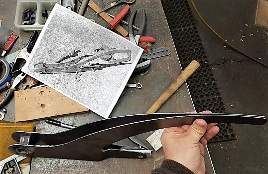
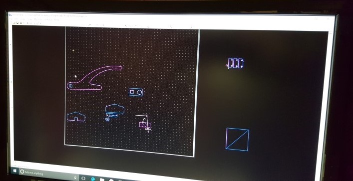
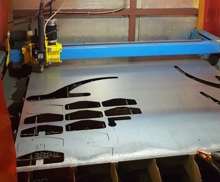
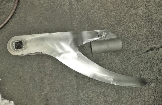
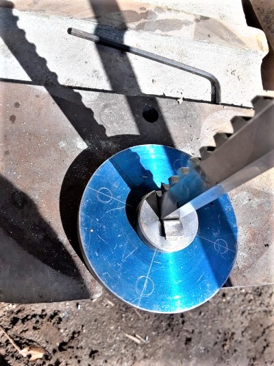
Here's a video of cutting the 1/8" stainless today with the plasma table. The rectangle is the top of the device arm. I initially thought 1/8 would not be sufficient but my friend recommended it so that's how we went. I'm glad now, it is plenty strong.
https://youtu.be/qqqn_7Q5_N4
Here is very short video of TiG welder tacking the top piece we cut out, onto the device arm. That's a liquid cooled welding torch. The original Dispro device looks like it was cast and this one is welded, but they will be pretty similar. This video shows our actual device. This gear should go nicely behind the Palmer YT1.
https://youtu.be/Xq_Iy_Y9-qw
enjoy |
narrabay
Member
Username: narrabay
Post Number: 4
Registered: 05-2016
| | Posted on Saturday, March 25, 2017 - 08:18 pm: |
|
Worked on the brake today. 147 days until Mystic. 
Video, cutting brake drum pieces:
https://youtu.be/lZXLYjVT3FU
 |
ned_l
Senior Member
Username: ned_l
Post Number: 120
Registered: 08-2012
| | Posted on Thursday, March 30, 2017 - 12:30 pm: |
|
Nice work. I'm enjoying following your build. |
narrabay
Member
Username: narrabay
Post Number: 8
Registered: 05-2016
| | Posted on Saturday, April 01, 2017 - 08:07 pm: |
|
thanks ned, that means a lot.
todays effort, actually the last couple weeks was on the "brake" setup. all it does is hold the arm down, or up. it needs to have the ability to slip if the skeg strikes an obstacle while under way. I suspect thats why the Dispro history book describes a switch from a push-pull post that has the cutless bearing on the bottom, to the arm system. the brake becoming the project lately! Sometimes it seems that we are buildinga brake that happens to have a Dispro and boat attached! But as you can see the benefits of having a precision plasma table allow for some decoration opportunities. The bracket shown here is my first attempt at TiG welding. I will make no claims other than it probably wont break! 
 |
narrabay
Member
Username: narrabay
Post Number: 9
Registered: 05-2016
| | Posted on Saturday, April 08, 2017 - 11:09 pm: |
|
Today we manual threaded the two brake attach posts and decided to try and make a oil seal holder ring that will screw into the side of the fiberglass housing and into the center bracket behind it. I am trying to source a standard shaft seal but that is stainless. Other ideas on sealing this shaft are welcome. The space between the drum "brake" and housing is minimal, maybe 1/2". The other side can simply have a domed cap that fastens over it, with a drain hole back to the sea.
Also weighed the components today and as follows:
11" Bronze 3 Blade Prop 3.9lbs
Device Arm with Cutlass 5.4
Center Bracket Assembly with Brake and Shaft 7.3
The Two Prop Shafts 10.8
Universal Joint 2.2
Fiberglass Housing w Stuffing Box 9.3
Total about 40lbs (not bad)
The original Dispro housing alone I'm told is 80-90lbs by itself.
My Dispro book describes the Waterman K1 engine as 70lbs IIRC, whereas the YT1 for this project weighs in at 205lbs with reverse gear.
So if my housing increases to 20lbs when reinforced with more fiberglass, and total weight is 50lbs then I'm at 255lbs without battery and fuel tank. Whereas the original Dispro would be 155lbs plus shaft, prop etc battery or magneto (whichever was used) and fuel, maybe 170?. So I'm up by around 85lbs lbs for the privilege of operating a four stroke engine with reverse gear.
TRIVIA: The original Dispro system weighs around the same as a modern 30hp outboard and my system is about the same as a 70hp outboard!
This boat is just under 12ft vs the 16-18ft (but narrower) Dispro hull.
Overall they at least very approximately compare. Still may move the gear to a larger hull if something turns up. Might even tie the engine bed to the housing and make it a bolt-to-the-bottom single unit. Just needs to look old, and work properly. |
narrabay
Member
Username: narrabay
Post Number: 13
Registered: 05-2016
| | Posted on Sunday, June 04, 2017 - 01:46 pm: |
|
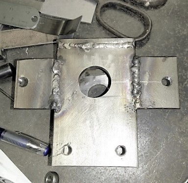
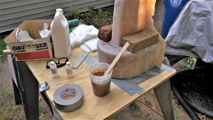
Finally got some time to this, started filling the channel where the center bracket lives. Fiberglass glass cloth and mat and resin, with bracket smooshed into it and allowed to cure. Followed by much hand working with a file. Also procured stainless round head fasteners 3/8"-16
 |
narrabay
Member
Username: narrabay
Post Number: 14
Registered: 05-2016
| | Posted on Friday, July 07, 2017 - 07:21 pm: |
|
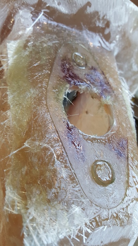
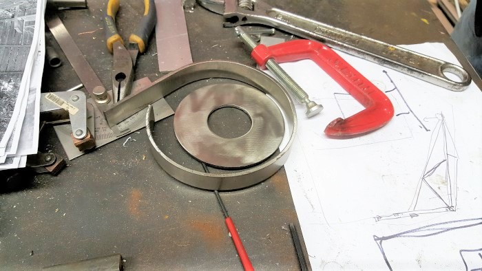
This is the seal I decided to try first. The brake disk collar will be welded to the center pivot shaft. We grooved the backside of the collar for the big O-ring, which will be greased. There will be shims to set the depth and thereby pressure on the O-ring. The other side has the other end of the center pivot shaft but i will make a cap for that (like a trailer hub's grease cap) so no need for a seal.
We also cut the keyways into the 2 prop shafts.
 |
narrabay
Member
Username: narrabay
Post Number: 16
Registered: 05-2016
| | Posted on Thursday, October 19, 2017 - 02:51 pm: |
|
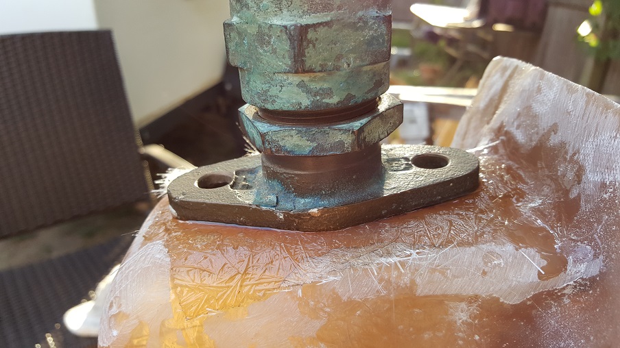
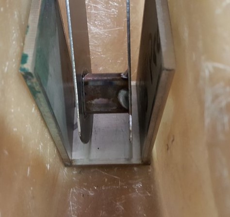
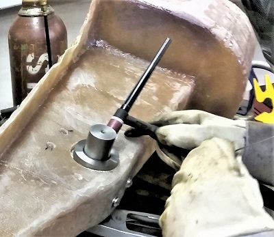
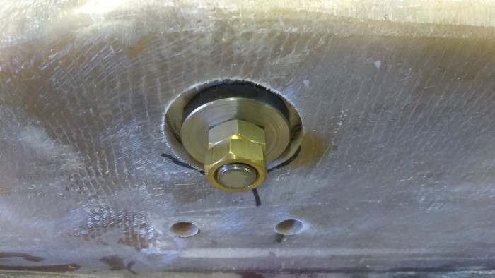
Finally got some time for this. Welded the collar onto the center pivot shaft so it is back about 1/8 from the bracket. That way when it is drawn by the retainer nut from the other side, it will squeeze that big O-ring, which will be greased. That makes the o-ring sort of a bearing but remember this only turns about 90 degrees when deploying or retracting the propeller. The retainer nut will have a stop nut as well so when the tension is pulled onto the o-ring it can be locked there.
IIRC, Miro may have mentioned that this sealing area was a major challenge on the original Dispro with a inadequate design deployed initially. Mine however just might be above the water line which should help.
If there are any suggestions to this such as the design, or what kind of grease to use that would be great.
While this will not be rotating, the vibration and imbalance of the prop along with the freeplay on the shaft hole will allow side to side movement, maybe even continuous. So we'll see if it develops leaking after some running time.
 |
narrabay
Member
Username: narrabay
Post Number: 17
Registered: 05-2016
| | Posted on Friday, October 20, 2017 - 10:25 pm: |
|
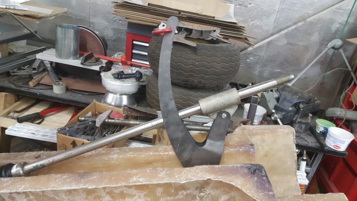
Finally, today we actuated the device for the first time. It worked very smoothly which surprised me. We made the lever which will get a wooden handle and the center of the brake will be teak or other wood. The o-ring seal gets squished by the tension on the brass nuts on the other side. There is no seal there, will simply make a water tight cap for that side with a drain hole in the bottom to the housing sea side. The center pin, brake drum, and handle are welded as one piece since it would never need to come apart. Unlike the original Dispro, the skeg does not extend under the prop. It should still push the prop up if hitting anything. If it jumps over and still hit an obstacle with the prop, I would consider next year making a new one that goes farther but this seems good for our waters. The original was made to survive logging wood in the rivers.
Youtube Video here: {https://youtu.be/1b98VVa0s5k}
 |
miro
Senior Member
Username: miro
Post Number: 938
Registered: 11-2001
| | Posted on Saturday, October 21, 2017 - 08:23 pm: |
|
I suggest that the grease that you should use on that O ring seal is water pup grease - it's really stiff - almost like a hard wax, but it does flow.
I use it on gear water pumps.
It won't take much. If you're stuck to find some, I can send you enough for a life time - about a teaspoon's worth.
miro |
narrabay
Member
Username: narrabay
Post Number: 18
Registered: 05-2016
| | Posted on Sunday, October 22, 2017 - 09:01 pm: |
|
thank you Miro, may just take u up on that. I am learning about this water pump grease. so far interesting info on it. |
narrabay
Member
Username: narrabay
Post Number: 19
Registered: 05-2016
| | Posted on Thursday, October 26, 2017 - 10:05 pm: |
|
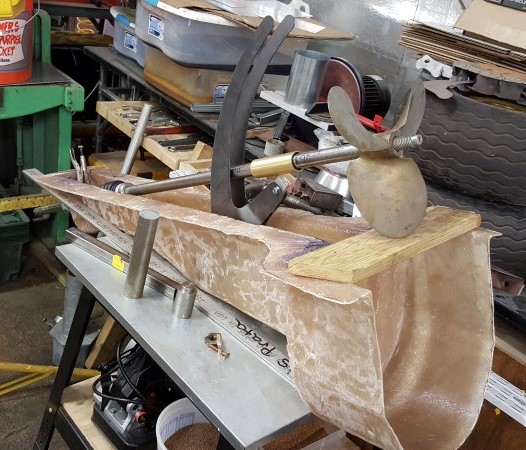
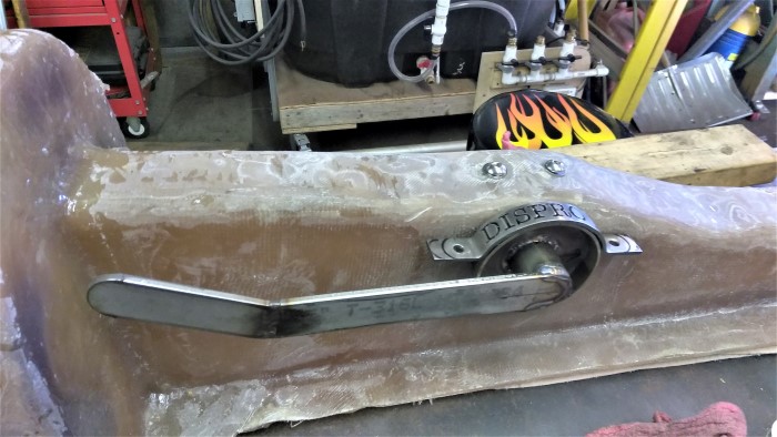
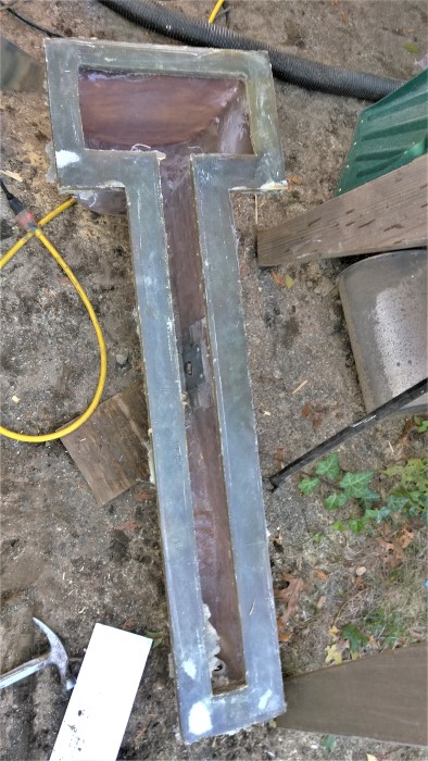
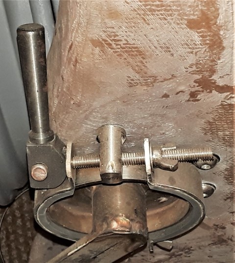
A little more progress. Changed the brake design to eliminate the springs and wing nuts, and instead use stacked washers (stainless) to adjust for clamping of the brake shoe and washers on the posts at the same time, with double nuts (jam nut) to fix in position. The springs had allowed the brake shoes to rotate a few degrees with the device. Now its stays still. Also added oak handle and cleaned up the housing some more. It's starting to look like something but much to do for example the arm moves a little too much side to side so I may have to enlarge the housing or install rubber guides inside the tunnel. A little clearance movement at the center pin turns in to more at the prop. Also need to install top and bottom travel stops as well. And need to make the water tight cover for the other side of the center pin where it sticks out of the housing. Also plan to close in the aft end of the housing like the original and run the mounting flange all the way around so it could be easily removed as needed. So we're 90% done with only 50% to go! 
Movie and Demo of original Dispro here:
https://vimeo.com/150567324
Movie of this "Dispro 2" movement action:
https://youtu.be/9qfYv0lKT9Q |
narrabay
Member
Username: narrabay
Post Number: 20
Registered: 05-2016
| | Posted on Tuesday, October 31, 2017 - 07:13 pm: |
|
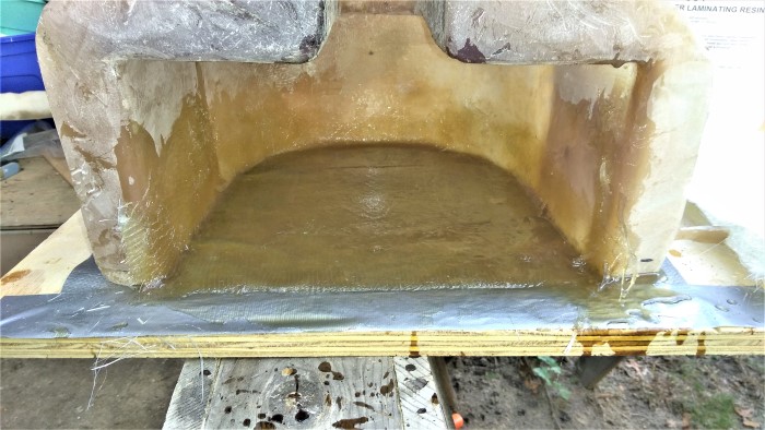
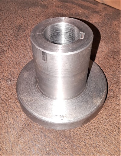
Someone suggested that I make the housing removable, which makes sense since this boat may turn out to be too small. So, closed in the back and created a nice thick flange.
 |
narrabay
Member
Username: narrabay
Post Number: 21
Registered: 05-2016
| | Posted on Tuesday, October 31, 2017 - 07:17 pm: |
|
couple dry spots I can wet later, but, not bad...
 |
narrabay
Member
Username: narrabay
Post Number: 22
Registered: 05-2016
| | Posted on Friday, November 03, 2017 - 01:28 am: |
|
Flange is nice and thick, a few voids to fill but nothing major. Housing with center bracket still weighs only 22lbs. Original bare housing was 90lbs (cast iron). Total weight incl propeller, etc around 50lbs.
 |
ned_l
Senior Member
Username: ned_l
Post Number: 159
Registered: 08-2012
| | Posted on Sunday, November 05, 2017 - 08:31 pm: |
|
Impressive! You are doing an amazing job. |
miro
Senior Member
Username: miro
Post Number: 939
Registered: 11-2001
| | Posted on Tuesday, November 07, 2017 - 09:13 pm: |
|
Looks like a descendant from the original 1915 patent - nice to see that inspiration can come from way way back.
I somehow thought that all that fiberglass would be heavier.
When you get the boat finished and find that you have insufficient ballast, I'm very willing to serve as additional ballast
miro |
narrabay
Member
Username: narrabay
Post Number: 23
Registered: 05-2016
| | Posted on Wednesday, November 08, 2017 - 01:46 pm: |
|
thanks guys. sure miro you are welcome here in RI anytime at all. |
narrabay
Member
Username: narrabay
Post Number: 25
Registered: 05-2016
| | Posted on Wednesday, March 07, 2018 - 12:15 pm: |
|
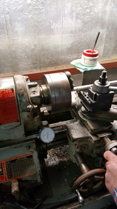
Have a lathe now, been working on making my first companion flange. I may do it again but this one is not bad, maybe even acceptable. making the 1/4" keyway would require a broach, which I have to get. dave mentioned up above doing it with the chuck locked but not sure about the tool holding end of that. may try to figure that out. also making a 304 stainless spacer for the center bracket that the device arm can rest in when down in the running position. this will provide for several benefits, a hard stop, control of any side to side motion, and additional strength for the center bracket not that it really needs it. as to the main character in this effort, the YT1, looking forward to putting the 'new' cylinder on, and also have a head-making project in the pipeline. The head seems ok, but we all know about corrosion issues and how they can progess unstoppably. Making a new head (and never letting it see salt water) will eliminate one vulnerability to this old engine.
 |
jim_parrott
Senior Member
Username: jim_parrott
Post Number: 179
Registered: 06-2009
| | Posted on Wednesday, March 07, 2018 - 08:30 pm: |
|
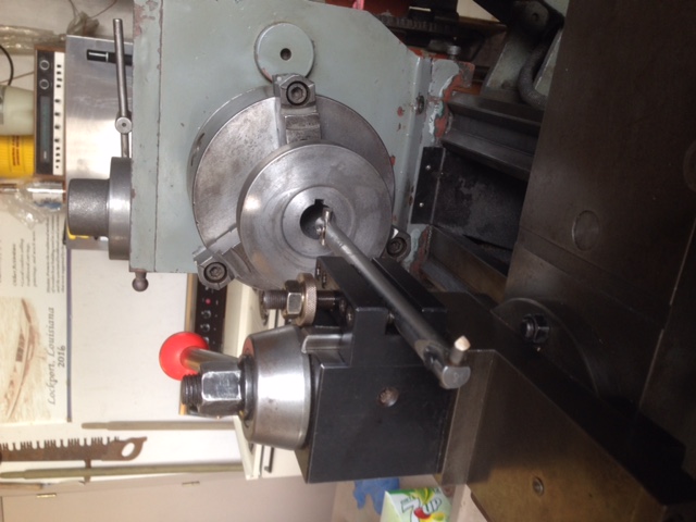
You can use a boring bar to cut your keyway. I just engage my back gear to hold the chuck.
 |
narrabay
Member
Username: narrabay
Post Number: 26
Registered: 05-2016
| | Posted on Wednesday, March 07, 2018 - 09:39 pm: |
|
thanks jim. my only boring bar is a 1/2" with carbide insert but I will look for one with a tool holder on the end like yours. (I am new at machining). thank you |
narrabay
Advanced Member
Username: narrabay
Post Number: 39
Registered: 05-2016
| | Posted on Saturday, April 07, 2018 - 03:50 pm: |
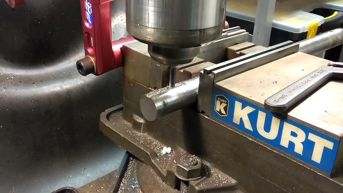
|
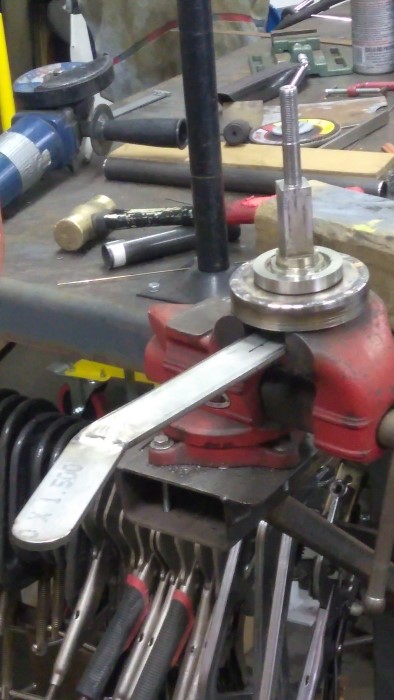
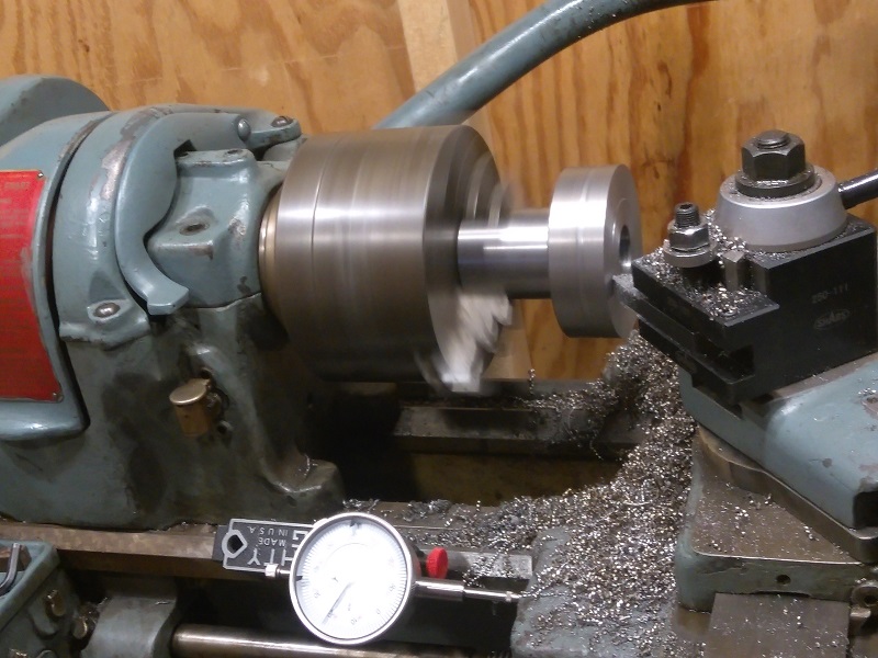
Got the keyway done and took the easy way out, got a Dumont broach from ebay and an unused Famco #3 arbor press from a buddy. I may look for a boring bar and make another keyway using jim's method too, to learn it. For now this will do. This flange is nice so far but the bore is not smooth and I went over .005" trying to smooth it out. Next one, the final cut will be made with a 1" carbide reamer that I picked up used. This one is good practice for me, being new at machining.
 |
narrabay
Senior Member
Username: narrabay
Post Number: 52
Registered: 05-2016
| | Posted on Saturday, July 13, 2019 - 03:21 pm: |
|
Well it's been over a year since my last post so I may as well give the update. Still need to re-engineer the brake mounting studs as I don't like the design... too small of a footprint. A thick washer may do the trick but I'd like something very strong like the rest of this Dispro design.
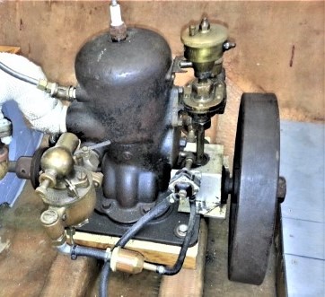
Also, I added an starter generator to the YT and it actually looks pretty good but now it's getting ridiculously heavy (250ish) for this 11 1/2ft dory so I think I will be using the Kermath Sea Pup instead and do without a reverse or neutral.
The YT is going into another hull.
Finally, I have STILL failed to accomplish making a shed addition for the Bridgeport Milling machine. That is coming.
Getting older sucks. Things always seem to hurt and progress gets really slow!
 |
narrabay2
Member
Username: narrabay2
Post Number: 30
Registered: 10-2019
| | Posted on Thursday, February 20, 2020 - 05:49 pm: |
|
Hi All, I saw Ernie today and he suggested update this topic since the project is still very much alive, but has a change. The heavy YT-1 engine is going into the Fantail (just picked up some 12 feet of 1" 304 SS prop shaft for that), and the Gray 3hp from the Fantail is going to drive the dispro. It is much much lighter and more appropriate for that smaller dory. This was actually Ernie's plan from before I bought the Yt from him. I think it makes a ton of sense.
 |
ned_l
Senior Member
Username: ned_l
Post Number: 209
Registered: 08-2012
| | Posted on Friday, February 21, 2020 - 12:39 pm: |
|
Very good, ..... that does sound like better fits for both. |